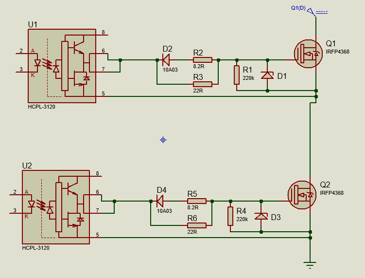
I was wondering if dead-time in a bridge design is achieved by the turn-on and turn off resistors as shown below, so that the FETs turn on slower and turn off faster, thus avoiding shoot through. Or does this need to be implemented in code?
2 Answers
Or does this need to be implemented in code?
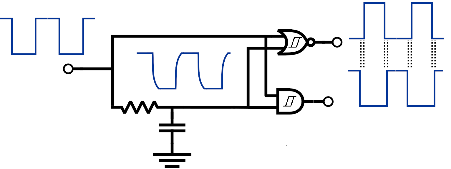
In the past I've used gates like this: -
It's fairly unambiguous in its ability to provide anti-shoot-through gate drives.
-
\$\begingroup\$ Thank you for your comment. When buying the NOR and AND gate for this topology, they must have the same propagation delay right ? \$\endgroup\$ Commented Jun 5, 2020 at 14:11
-
\$\begingroup\$ Most gates these days will have propagation times in the sub 10 nano seconds so any difference will be a minor error term compared to the likely (much larger) dead-time you require. Make sure you get schmitt trigger type gates as per the symbol inside the gates. \$\endgroup\$– Andy akaCommented Jun 5, 2020 at 14:14
-
\$\begingroup\$ Basically I am struggling to understand some stuff. I used the equation Ig = Q/t to calculate the gate current. for 't' I took the value from the MOSFETs datasheet which was (t-rise+t-on = 260ns), this gave me a value for current (Ig = Q/260ns) , and than I calculated the turn on gate resistor (R-on). Than i chose a value 1/3 smaller than the on resistor to ensure the FET turns off faster, is this not the dead time? \$\endgroup\$ Commented Jun 5, 2020 at 15:41
-
1
-
1\$\begingroup\$ Love it. Needed to add dead time for a high speed analogue current controller. That will do the trick! \$\endgroup\$ Commented Jun 8, 2023 at 3:10
You are right that the diodes make turn-off faster than turn-on. By making the turn-off transition faster than turn-on, that may be sufficient to prevent shoot-through in some designs. It will depend on delays and transition times inherent in the driver, the threshold voltages of Q1 and Q2, and so on.
While this is sufficient for some designs, it's not always ideal. Slowing the transition reduces efficiency, and by the time the transition has been slowed enough to avoid shoot-through, efficiency may have been unacceptably degraded. In that case the designer will opt to postpone turn-on by delaying the control signal to the driver, often with code in a microcontroller but of course simple discrete solutions are also possible.
So to answer your question, designs may use code, asymmetric drive capability, or both to avoid shoot-through, depending on requirements.
-
\$\begingroup\$ Thank you Phil for your comment. My Optos have a maximum propagation delay of 200ns. The rise time of my FETs are 250ns and fall time is 430ns. The gate threshold voltage is 2V. From this how can I determine the dead-time required? \$\endgroup\$ Commented Jun 5, 2020 at 13:52
-
\$\begingroup\$ @DanielBashy Simulation, build it and tweak it empirically, or just make some estimates and add some margin and call it good enough. It's up to you. \$\endgroup\$ Commented Jun 5, 2020 at 18:51


