1
\$\begingroup\$

I am driving an optical modulator with a driving signal with DC(2 V)+RF signal(bandpass signal from 1GHz to 2GHz, 500 mVpp). The DC and RF are combined with a bias-tee (mini-circuit, ZFBT-6G+). The passband of the RF port of this bias-tee is 10 MHz to 6 GHz.

However, I would like to add a 1 kHz sinusoid dither signal to the driving signal, to monitor the working status of the modulator. The problem is, 1 kHz is too low for the RF port of the bias-tee.

Is there any suggestion on this?

Intuitively I came up with the idea to feed in the dither from the DC port, not the RF port. I tried to search whether the DC port of the bias-tee can get the 1 kHz dither in but google did not give me any clue.

Thanks in advance.

\$\endgroup\$
2
  • \$\begingroup\$ Have you tried applying the 1 kHz signal to the DC port? What happened? \$\endgroup\$
    – The Photon
    Commented Aug 21, 2020 at 21:16
  • \$\begingroup\$ Not yet. I would like to try this out soon. \$\endgroup\$
    – Shawn
    Commented Aug 22, 2020 at 2:28

2 Answers 2

1
\$\begingroup\$
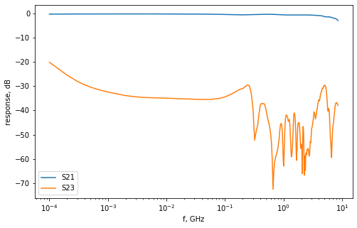
  1. You could try applying the 1 kHz signal to the DC port of the bias tee and see if it passes through to the RF+DC port. Unfortunately the s-parameters provided by Mini-Circuits only cover down to 100 kHz, so it's hard to tell in advance how well this will work.

  2. If that doesn't work, you could look for a different bias tee with more bandwidth in the path from DC to RF+DC.

  3. You could design your own bias tee specifically to allow ~1 kHz signals through from the DC port to the output port. Or you could design a network with 3 input ports (RF, 1 kHz, and DC) and one output port combining these signals.

For the record, here is the insertion loss for your chosen bias tee, from RF to RF+DC (S21), and from DC to RF+DC (S23) according to the s-parameters provided by Mini-Circuits: enter image description here

\$\endgroup\$
1
  • \$\begingroup\$ Yes, that was what I read, no 1 kHz shown. I could not push the dither to higher as my feedback does not support. I'll try adding it to the DC. Thanks! \$\endgroup\$
    – Shawn
    Commented Aug 22, 2020 at 2:27
0
\$\begingroup\$

The DC port can be dithered all you want (!)

enter image description here

Although it's purpose is to remove noise for DC Bias at RF not audio range from RF with 20 to 50 dB isolation between DC and both RF ports. this may be useful if modulator has stiction or hysteresis (rare).

\$\endgroup\$
2
  • \$\begingroup\$ Thanks! I'll give it a try \$\endgroup\$
    – Shawn
    Commented Aug 22, 2020 at 2:25
  • \$\begingroup\$ In HDD servo's they sweep from high f to low f which increases amplitude to overcome stiction on spin up so heads do not rip off before revving up to huge RPM's then remove dither once moved and then spin up with huge g's. \$\endgroup\$
    – D.A.S.
    Commented Aug 22, 2020 at 2:30

Your Answer

By clicking “Post Your Answer”, you agree to our terms of service and acknowledge you have read our privacy policy.

Not the answer you're looking for? Browse other questions tagged or ask your own question.