0
\$\begingroup\$

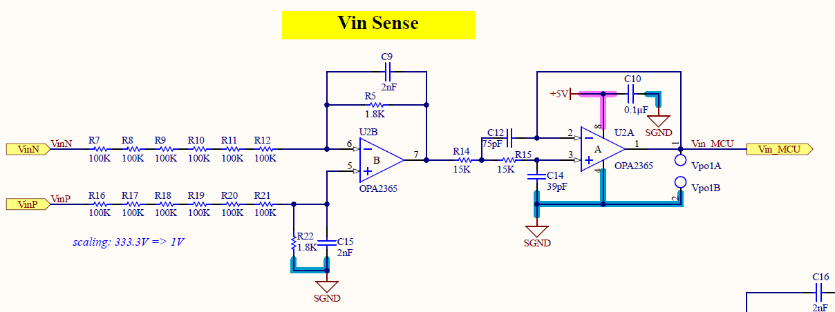
I have the following voltage sensor to place in a layout of a low voltage converter (800 V dc link).

The input voltage dividers need to be located in the power-stage section of the PCB. The question is as follows: should the differential + LPF opamps be located close to the control stage or should they be close to the voltage dividers?

Pros of being close to the voltage divider: the second output has a low-impedance path to the controller.

Pros of being close to the controller: possible noise pickup on the Vin_MCU trace is quite low.

This will be a hard-switched converter.

enter image description here

\$\endgroup\$
2
  • \$\begingroup\$ If your differential traces are run close together effectively as a differential pair, then I would say put the low-pass filter and dif amplifier closer to your microcontroller... Although based on your filter components for your diff amp, it seems like if you're limiting noise 100 hz and below you probably won't get a ton... \$\endgroup\$
    – MadHatter
    Commented Aug 27, 2020 at 14:04
  • \$\begingroup\$ The lowest impedance to stray noise should be on your longest cable. \$\endgroup\$
    – D.A.S.
    Commented Aug 27, 2020 at 14:25

1 Answer 1

1
\$\begingroup\$

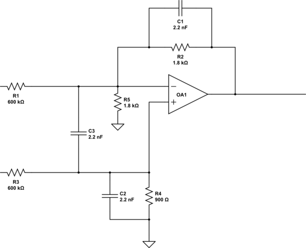
Not so sure, your difference amplifier would work as you intend.

schematic

simulate this circuit – Schematic created using CircuitLab

IMO the above circuit is "closer" to an differential voltage probe amplifier. C3 forms a filter for common mode pulse. I have seen use of this circuit for monitoring DC bus voltage of solid state tesla coil.

Simulator without capacitors, it prooves the symetry of voltage sensing

As for your question, I would place the 600k resistors externally on the DC bus for safety reasons.

\$\endgroup\$

Your Answer

By clicking “Post Your Answer”, you agree to our terms of service and acknowledge you have read our privacy policy.

Not the answer you're looking for? Browse other questions tagged or ask your own question.