0
\$\begingroup\$

I am testing my new PYNQ Z2 FPGA board with an external DAC and ADC connected. The datasheet for the converters says they are 12 bit, they are able to differentiate between 1 mV and has a range of 0-2 Volts. The handling of data between the board and conversters is in code that comes ready written with the board. I am no expert, so I have not yet found out how that is done, if it uses all the 12 bits, etc.

The only thing I am able to see now is values I write in Python to the DAC and values read in on the ADC. I was wondering if I am able to say something about the error just from these values. If the error is due to noise from the electrical mains or if some of the converters simply are gone bad.

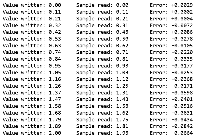
The error seem to get bigger and bigger as the values increase. Here is a test with 20 values between 0 and 2 V. If I run the test two times, all the values are exactly the same. Could this be because the software written doesnt make use of all the bits, or is that not possible to say?

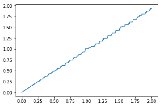
A plot where 500 points are used at the bottom.

Any hint is greatly appreciated!

enter image description here

enter image description here

\$\endgroup\$
6
  • \$\begingroup\$ In your graph, the X-axis is the value you write to the DAC and the Y-axis is the value you read from the ADC, am I right ? Also do you have the reference of the ADC and DAC you are using ? \$\endgroup\$
    – Genorme
    Commented Sep 1, 2020 at 8:27
  • \$\begingroup\$ Yes that is right. The DAC has a reference voltage of 1.25 V and ADC has a reference voltage of 2.048 V. ADC: (reference.digilentinc.com/_media/reference/pmod/pmodad2/…) DAC: (reference.digilentinc.com/_media/reference/pmod/pmodda4/…) \$\endgroup\$
    – Une
    Commented Sep 1, 2020 at 8:58
  • \$\begingroup\$ You need to use an accurate DVM and measure the DAC output voltage against values supposedly produced. \$\endgroup\$
    – Andy aka
    Commented Sep 1, 2020 at 9:27
  • \$\begingroup\$ Yes then if it is only one of them causing the big error then its probably not because of low bits used. Lets say its just the DAC making the error, would you then conclude that its probably not due to low bits used (code for the two converters is written by the same supplier) and that its probably faulty and get a new one? Sorry if im asking banal questions here.. \$\endgroup\$
    – Une
    Commented Sep 1, 2020 at 9:55
  • \$\begingroup\$ @Une Measure it - I'm not speculating. \$\endgroup\$
    – Andy aka
    Commented Sep 1, 2020 at 10:22

1 Answer 1

1
\$\begingroup\$

What you are observing are actually missing codes, it is a hardware related issue that can come from the DAC and/or the ADC. It is not coming from your software. You can have a look at this question that explains a similar issue.

What you can do first is to ensure that the DAC voltage settling time is respected before you launch a conversion on the ADC side.

If you can test other ADC architectures, I suggest to do so. The ADC you are using is built around a successive-approximation-register algorithm. Depending on your specifications, you may find a sigma-delta or a pipeline ADC that can fits your needs.

You can read this paper that describes the non-linearity issue and you can refer to this page just to ensure you are using the right ADC for your application.

\$\endgroup\$

Your Answer

By clicking “Post Your Answer”, you agree to our terms of service and acknowledge you have read our privacy policy.

Not the answer you're looking for? Browse other questions tagged or ask your own question.