1
\$\begingroup\$

I'm trying to make an inverter (DC to AC), for a university class project.

The DC source is powered from two DC batteries 12V each, then this provides energy to a SPWM generator which then goes to an H-bridge, then a transformer, and finally to a lowpass filter.

My problem begins with Proteus. When I try to make a battery level indicator, it has to be one for each battery. Besides that, ground must be connected between the (-) terminal of the first battery and the (+) terminal of the second one.

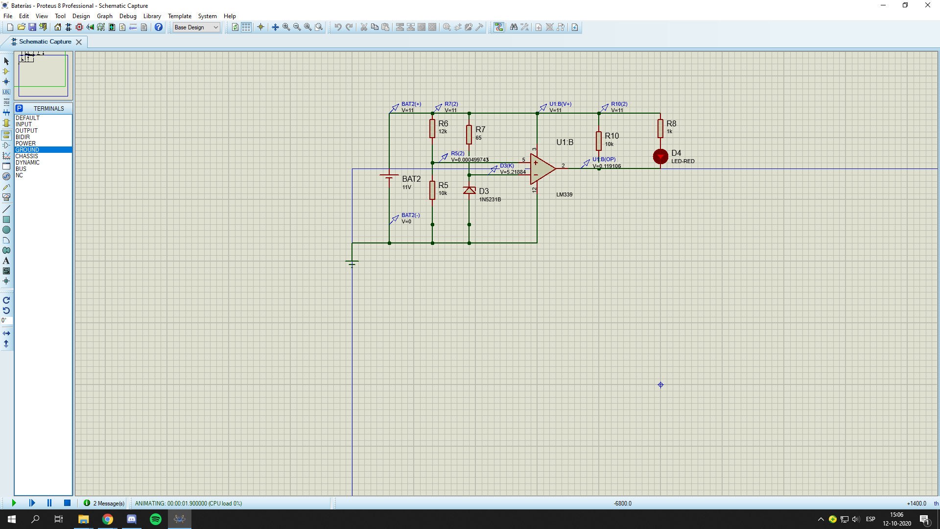
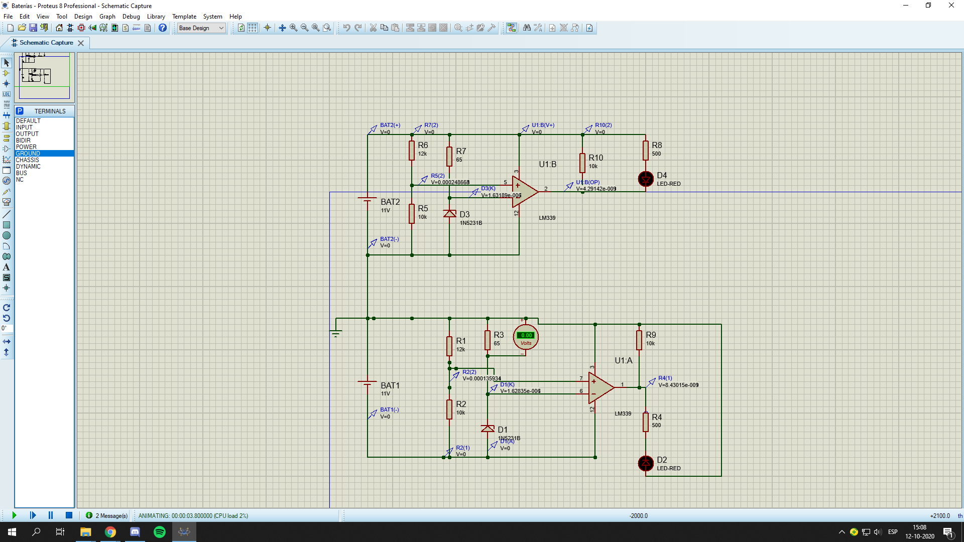
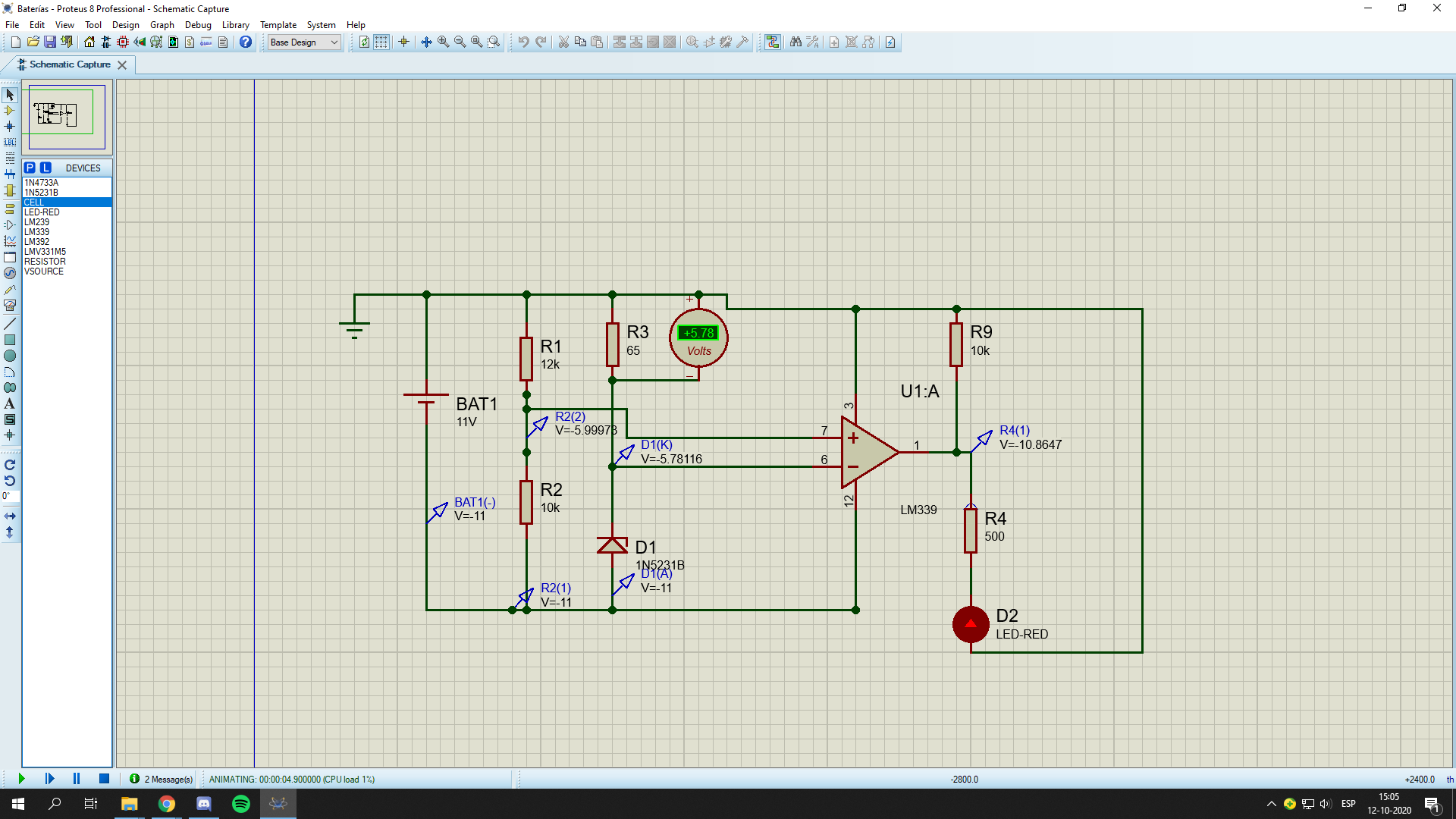
In picture 1 and 2 are the circuits working for each battery, but when I try to connect both with the two batteries connected and the ground, it goes all to 0V as seen in picture 3.

What do I need to do to solve this, but meeting the requirements -ground between the two batteries and a battery level indicator system for each battery. The LEDs are supposed to turn on when the battery level is less than 11V.

enter image description hereenter image description hereenter image description here

\$\endgroup\$
5
  • \$\begingroup\$ Your schematic shows pin 3 of the comparator connected to both +supply and ground, and pin 12 connected to both ground and negative supply, shorting both supplies to ground. \$\endgroup\$ Commented Oct 12, 2020 at 18:58
  • \$\begingroup\$ So how should i connect it? \$\endgroup\$ Commented Oct 12, 2020 at 19:08
  • \$\begingroup\$ You could use two comparator chips, one for each polarity. \$\endgroup\$ Commented Oct 12, 2020 at 19:14
  • \$\begingroup\$ thats what im trying to do, could you upload a picture please ? \$\endgroup\$ Commented Oct 12, 2020 at 19:17
  • \$\begingroup\$ According to the schematic, you are trying to use the two comparators in one LM339 - you need to use two separate LM339s, using one comoparator in each, with the one sensing the positive voltage powered by the positive supply, and the one sensing the negative voltage powered by the negative supply. \$\endgroup\$ Commented Oct 12, 2020 at 21:40

1 Answer 1

0
\$\begingroup\$

You are choosing a dual Op Amp comparator correctly but not choosing a differential input to bias -Vbat as a a differential amp with positive bias to reach Vin >=0 for common mode. The voltage divider must be biased to +Vcc and not 0V for -Vbat to be compared. then output on both LEDs is >0V so you do not connect Anode to 0V but rather and comparator switches to 0V not -Vee. This a common design flaw.

\$\endgroup\$
2
  • \$\begingroup\$ So what should i do ? i didnt get it \$\endgroup\$ Commented Oct 12, 2020 at 18:50
  • \$\begingroup\$ Learn how to use a differential amplifier with 4 resistors so that you scale Vdiff and move Vcm into allowed range >=Vee=0V. Schematic error shorts out V- battery with pin 12 shared , so only use V+,0V for power \$\endgroup\$
    – D.A.S.
    Commented Oct 12, 2020 at 19:47

Your Answer

By clicking “Post Your Answer”, you agree to our terms of service and acknowledge you have read our privacy policy.

Not the answer you're looking for? Browse other questions tagged or ask your own question.