0
\$\begingroup\$

I've been tasked with massivly expanding some GPIO of a microcontroller, and my inital thought was to chain a bunch of SN74HC595 and SN74HC597 shift registers, however to get the ammount that's required I'm looking at 32x PISO and 32x SIPO shift registers. This seems like a lot and I'm concerned about a few things....

  1. Would the 25mA Sink/Source of my Micocontroller be enough to drive all 32x clocks/latches/resets..etc? If not, could I use a number of buffers to drive blocks of 8x shift registers in parallel? Such as below?

  2. I'm assuming as long as the shifting/clocking of data through the chain isn't too fast I can limit the effects of propergation delays?

  3. Anything I've missed that I should be worried about? It seems wacky but in principle ok? Any particular design or layout considerations?

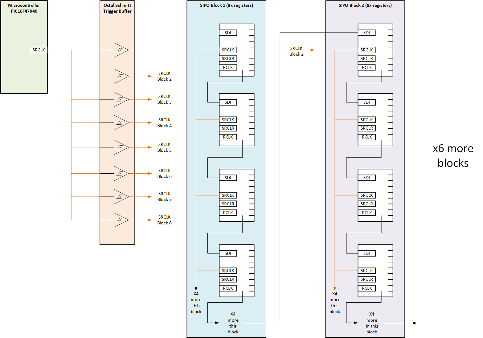
enter image description here

\$\endgroup\$
1
  • \$\begingroup\$ Which microcontroller? You need to look at how much capacitive load the MCU output can drive and whether sum of expander chip inputs is within limits, or that with the given capacitive load the slew rate is still fast enough for the expander chips. Too slow edges will cause problems. The clock speed needs to be slow enough to allow the expander output to update to next expander input, also found in datasheet. \$\endgroup\$
    – Justme
    Commented Mar 8, 2021 at 18:02

1 Answer 1

1
\$\begingroup\$

There are some (potential) problems, these I can think of right now:

  • depending on what you are doing with that many outputs, you might get significant ground currents, which can mess with your ground voltage relative to an output (ground raise, ground bounce)

  • these shift registers have fundamental problem when chained: the output that you have for chaining changes on the same edge as used by the next chip for sampling its input. (Chips that are designed for chaining have an opposite-edge chain data output.) This creates a (potentional) data race. Solutions are a) delaying the data (R+C), or b) feeding the clock from the FAR end.

  • 32 or 64 clock inputs is quite a capacitive load. Consider using distributed buffers, or a high-capacity buffer (check drivers that are meant for power mosfet gates) BUT sharper edges create more reflections (which you don't want on a clock line, the data lines are less problematic), so you might need to add series resistors to combat false clocks due to reflections.

I dunno what you want to do, but if it is driving lots of LEDs you might consider other options, like neopixels, max7219 (64 LEDs per chip, up to 8 chips chained), or driving a LED matrix directly.

\$\endgroup\$
1
  • \$\begingroup\$ Thanks for the reply. The intention is for these outputs to drive some MOSFETs to switch relays, so the outputs of the shift registers aren't driving much of a load, but I assume your point is everything changing at the same time could induce ground currents and upset things. Regarding the output changing on the same edge as the clock creating a race on the chained input, are there better shift registers you can suggest for this? Finally, would my circuit shown in the diagram using buffers help resolve the problem with capacitive loads? \$\endgroup\$ Commented Mar 8, 2021 at 23:48

Your Answer

By clicking “Post Your Answer”, you agree to our terms of service and acknowledge you have read our privacy policy.

Not the answer you're looking for? Browse other questions tagged or ask your own question.