I am looking for a solution for shifting signal in 0V to 5V range to -2,5V - 2,5V range. I can design a solution for AC with filter - where I remove the DC offset by a RC filter and add amplification (compensation). But I need a DC solution. Any tips?
-
1\$\begingroup\$ Meanwhile I have designed something like this (resistor values are just for ratio purposes) - cl.ly/MKHe \$\endgroup\$– mrkvaCommented Jan 21, 2013 at 14:17
-
1\$\begingroup\$ What frequency range are you working with? \$\endgroup\$– Matt YoungCommented Jan 21, 2013 at 14:31
-
\$\begingroup\$ do you have +/- voltage rails available? \$\endgroup\$– vicatcuCommented Jan 21, 2013 at 14:33
-
\$\begingroup\$ I would like to include all signals, including DC. I have +/- voltage rails available. \$\endgroup\$– mrkvaCommented Jan 21, 2013 at 14:36
3 Answers
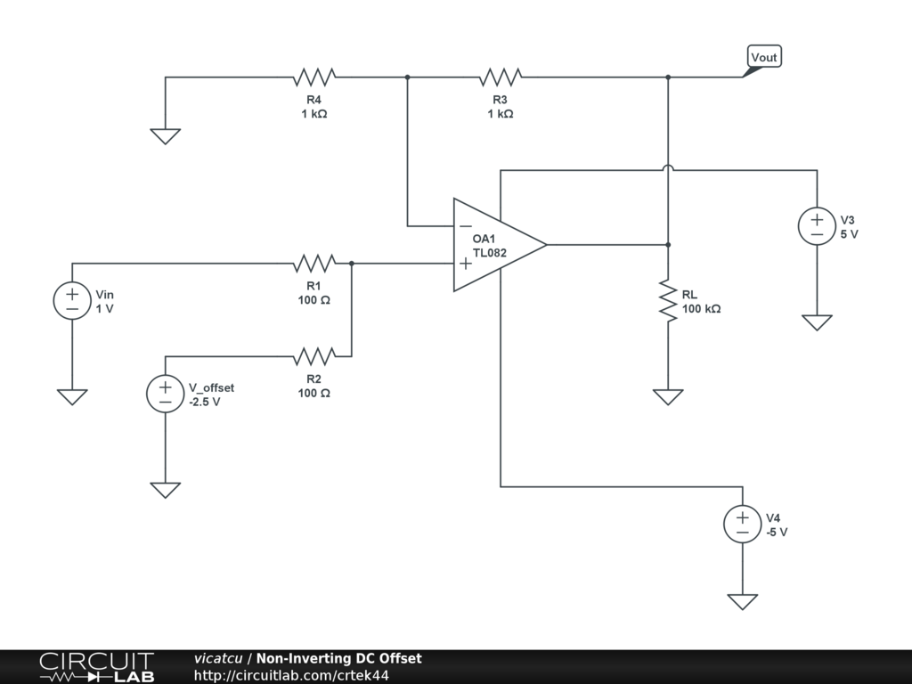
You can use an op-amp, in a non-inverted summing configuration as I've illustrated in circuitlab here. You would simply need to provide the -2.5V for V_offset (for example using a voltage divider, precision voltage reference, or whatever). If you run a linear DC-sweep of Vin from 0 to 5V you'll see that Vout varies linearly from -2.5 to +2.5V. I've included an image of the circuit here for completeness.

-
\$\begingroup\$ I would like it if someone could expand upon the selection of R1 and R2 values in the proposed circuit. \$\endgroup\$– vicatcuCommented Jan 21, 2013 at 16:46
-
\$\begingroup\$ In this application it's important that R1 and R2 are equal. Making them small will more heavily load the voltage sources Vin and V_offset, because they will have to source or sink more current to maintain their voltages. Making R1 and R2 bigger will increase errors due to the small, but non-zero input current to the op-amp. TL082 input impedance is really high; R1 and R2 could easily be \$1M\Omega\$. \$\endgroup\$ Commented Jan 21, 2013 at 17:45
Quite often, if you examine the use of the +/-2.5V signal, you may find you don't need to : you may be able to generate a local "0V" signal (which is really 2.5V DC) and leave your input signal unchanged. The local 0V reference can be as simple as 2 equal resistors and a decoupling capacitor; or if you need to draw significant current from it you can buffer the same circuit with an opamp.
Whether you can do this depends on your application. But if it eliminates a power supply it's worth considering.
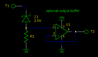
A reversed-biased zener diode makes a simple voltage source, which you can subtract from your input by putting it in series with it:

With the output buffer, R1 can be pretty big to avoid loading the source too much, but you must keep R1 small enough so that the current is sufficient to keep the current in Z1 high enough to get a stable voltage. See your selected diode's datasheet for that current. Without the output buffer, your selection of R1 will be dependent on the impedance of the devices connected to the inputs and the outputs.
Of course, zener diodes aren't the most accurate voltage references, and the voltage varies a little with current, but if your application doesn't demand that accuracy, it's hard to get simpler than this circuit.
-
\$\begingroup\$ z1 is not at it's operating range my friend. Why you use 1MOhm there? \$\endgroup\$ Commented Jan 28, 2013 at 16:02
