Can you show me how can I make a schematic to convert signal voltage from sensor to ADC module of DSP.
Sensor : -4 to 4 voltage DSP ADC: 0 to 3.3 voltage.
Thank you,
Can you show me how can I make a schematic to convert signal voltage from sensor to ADC module of DSP.
Sensor : -4 to 4 voltage DSP ADC: 0 to 3.3 voltage.
Thank you,
Since you are converting from a certain voltage range to a smaller range, with that smaller range entirely within the input range, it appears you could get by with a simple voltage divider. The only trick is figuring out the details.
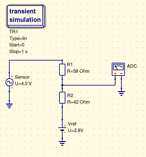
With +4 --> 3.3, and -4 --> 0.0, and assuming a simple linear map, we can figure that an input voltage of 2.8V should give an output (your ADC input) of the same. So, the voltage divider's "ground" should really be set at 2.8V. Then, any input voltage deviating from that amount, let's say +4.0V, which deviates by 1.2V, should be cut down to 3.3V, which deviates from the 2.8V by 0.5V - this tells us that your voltage divider must cut the signal down to (0.5)/(1.2) = 0.417 Using resistors 58ohm and 42 ohm will do the job. (I have no idea what your sensor and ADC impedances are, but you probably will want to scale up those resistors, 58K and 42K maybe.)

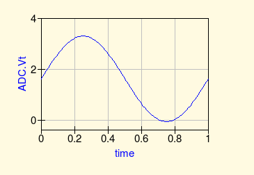
As a quick demo, I ran a simulation in QUCS using 4V peak sine wave, that is, varying from +4.0 to -4.0, and plotted the ADC reading (depicted by old-fashioned voltmeter symbol). As you can see, it goes from 0 to 3.3V.

The only detail I leave open to you is where to get 2.8V from. You could use another voltage divider between gnd and the +3.3V supply, so you have a network of four resistors. Such a divider will be loaded by R1, R2 and the sensor, but by tweaking the values you can make it work. Or, use an op amp voltage follower for a firm 2.8V that won't suffer from loading. Or, whatever else works in the context of the whole design.