3
\$\begingroup\$

I am working on a project which requires reading from four sensors simultaneously with time stamps down to millisecond.

Right now the best I can come up with is to use four PICs to read from each sensor and output through four RS232 to a laptop. So those sensors don't interfere with each other. For time stamps, I use a mechanical switch to trigger a external pin voltage change interrupt to start timers in all PICs at the same time. Timers increment every one millisecond and I just simply append the value from timers at the end of every measurement and output them through serial ports.

It works but I just want to know if there is a better solution since this project is kind of time critical (1000 measurements per second required). And also internal timer for each PIC varies which defeats the purpose of synchronizing timers.

I also thought about just reading from one additional chip's timer using SPI so all time stamps come from one source. However, I don't know when those PICs will read the time from that source chip. There could be four PICs reading from it at the same time which will mess up time stamps.

Sensor 1: Quadrature encoder (channel A B and Index)

Sensor 2: Laser (sending measurement back through Rs232 interface)

Sensor 3: accelerometer (analogue)

Sensor 4: inclinometer (RS232 interface)

I am using four DSPIC30f4011 chips. They have QIEs enough UARTs and also support four channel simultaneous ADC.

For Quadrature encoder, I use an on chip QIE to read from it and send measurement to a laptop through UART.

For Lazer and inclinometer, I read from them through UART1 and send measurements to a laptop through UART2.(one chip for each of them)

For accelerometer, x y and z information are being collected using four channel simultaneous mode. Measurements are sent to a laptop through UART.

\$\endgroup\$
5
  • 1
    \$\begingroup\$ I was about to suggest pretty much what you've done until I re-read the question. If they drift I guess you're using the internal RC clock? If the chips are all physically close enough you could look at driving them all from a single clock source. \$\endgroup\$
    – PeterJ
    Commented Feb 25, 2013 at 5:22
  • 4
    \$\begingroup\$ How do the sensors output their data? (e.g. analogue, SPI, I2C, parallel?) \$\endgroup\$
    – Oli Glaser
    Commented Feb 25, 2013 at 8:35
  • 1
    \$\begingroup\$ @PeterJ Do you think one crystal can drive four chips? How close should it usually be? \$\endgroup\$ Commented Feb 25, 2013 at 14:24
  • \$\begingroup\$ @OliGlaser just edited the question with more details on sensors. \$\endgroup\$ Commented Feb 25, 2013 at 14:34
  • 1
    \$\begingroup\$ @Timtianyang - good call, you should be able to clock all chips from one source, even if you chain the devices so only 1 chip runs from the xtal and the others run from its derived clock pulses. \$\endgroup\$
    – John U
    Commented Feb 25, 2013 at 14:58

3 Answers 3

1
\$\begingroup\$

Okay, we have some info on the sensors.

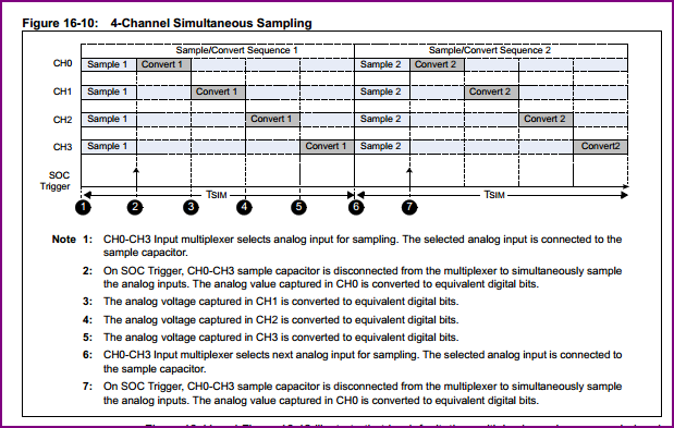
This should be doable with one of the newer dsPIC33Fs. As @gbarry correctly notes, they have variants that can do 4 channel simultaneous sampling (i.e. they have 4 sample and holds)

dsPIC sim samp

I am currently using one of these for some experimentation, the dsPIC33FJ64GP802. It's an impressive little chip, much better than the older dsPIC30F4011s. It runs at up to 40 MIPs, and has an 8-channel DMA which you can use for the ADC and other peripherals, so getting your timing within spec should be not so hard. The DMA makes life much easier, you can use it plus interrupts to save your main loop as much as time as possible.
You also have 2 UARTs, and 4 capture/compares (for the quad encoder) plus 5 timers.

You are missing 1 UART, so you will neither need to bit bang or add an external UART IC if you can't find a variant with more than 2 UARTs.

There are a few versions to choose from, the one I linked to is one of the smaller ones memory wise (I was mainly interested in the ADC and audio DAC plus DMA for audio ideas prototyping), so have a browse through all the options.

\$\endgroup\$
1
\$\begingroup\$

Why not use ONE micro with FOUR ADC's (not a hard thing to find) that reads all four values at once, then reports the data back over ONE serial link?

Without more detail about your setup I suspect you're deluding yourself about your ability to get 1mS accuracy/synchronisation too.

Edited to add: If you can give more detail about the application there are lots of other solutions; 1ksps is easily doable through the laptop sound-card (most will do 96kHz/16-bit on 2-channels, many can manage better / more channels).

Edit now we have more info:

Sensor 1: Quadrature encoder = 3 GPIO pins (as A,B,I are just logic levels)

Sensor 2: Lazer = 1 UART

Sensor 3: accelerometer = 4x ADC's

Sensor 4: inclinometer = Another UART

Connection to base: = Another UART

So that's 3 GPIO, 4 ADC and 3 UART - which is doable with ONE of your current PIC devcies, if you're willing to bit-bang an extra UART port (plenty of PIC bit-bang UART routines on the google). It would be easier using a single chip that has a spare UART or some other port, but perhaps your inclinometer or laser could use SPI/I2C? Just a thought.

I'd question your specification for the synchronisation of any of this (given the sample->conversion->UART->PIC->UART path for the Laser & Inclinometer), it seems to me everything will be subject to different amounts of delay, even if the data is reported back in one hit every 1mS it's likely to be out-of-sync with itself by some degree.

\$\endgroup\$
8
  • \$\begingroup\$ I can't think of a common microcontroller with four ADCs, only ones with four multiplexed analog inputs to a single ADC that take readings sequentially. But granted it may be an option for 1Ksps depending on what delays between readings can be tolerated. \$\endgroup\$
    – PeterJ
    Commented Feb 25, 2013 at 10:14
  • \$\begingroup\$ It depends how close you need it, plenty of micros out there with muxed ADC's that could take readings from 4 or more channels within a microsecond of each other, the micro we use (MCF52259) specs: 8x 12-bit ADC channels, up to 1.66 million samples per second, single conversion time of 8.5 ADC clock cycles (=1.7 μs), 8 conversions in 26.5 ADC clocks (=5.3 μs) using simultaneous mode. And that's not really its speciality, nor is it particularly fast (80MHz max). \$\endgroup\$
    – John U
    Commented Feb 25, 2013 at 10:25
  • \$\begingroup\$ @JohnU just edited the question with more details on sensors \$\endgroup\$ Commented Feb 25, 2013 at 14:35
  • 1
    \$\begingroup\$ It looks like the dsPIC33 line has parts that can take four ADC readings simultaneously. \$\endgroup\$
    – gbarry
    Commented Feb 25, 2013 at 15:50
  • \$\begingroup\$ If I use one chip for all sensors, will the measurements be collected sequentially? Ex sensor 1 --> sensor 2 --> sensor 3-->.sensor 4. There is a potential time difference between reading from the first and last sensor. I also need to to output collected data which will slow down the main loop more. How do u solve that? \$\endgroup\$ Commented Feb 26, 2013 at 14:10
1
\$\begingroup\$

Would an FPGA solution be possible? I'd imagine an FPGA, as a true multi-tasking capable hardware solution, would be able to process and encode all four signals in parallel quite easily. Four independent PICs with independent clocks sounds like a recipe for timing hell.

I'd recommend the Papillio. Bit of a learning curve if you've never developed for FPGAs before but they're pretty powerful in certain scenarios.

\$\endgroup\$

Your Answer

By clicking “Post Your Answer”, you agree to our terms of service and acknowledge you have read our privacy policy.

Not the answer you're looking for? Browse other questions tagged or ask your own question.