I know that voltage and current are measured with voltmeter and ammeter, but how is the frequenc measured in power grid applications? I know that a phase locked loop (PLL) can be used, but is this method also used for power grid applications? What is the most used instrument to measure it?
-
1\$\begingroup\$ NB: note that frequency is "important", but the "number" of periods over 1 day is "crucial" for old "mechanical" clocks. \$\endgroup\$– Antonio51Commented Mar 22, 2022 at 13:34
-
2\$\begingroup\$ This presentation by Bogdan Kasztenny shows you how some newer protective relays do it. Find his paper for details. \$\endgroup\$– relayman357Commented Mar 22, 2022 at 16:09
3 Answers
There are many ways to measure frequency, the choice usually being made on what technology is available.
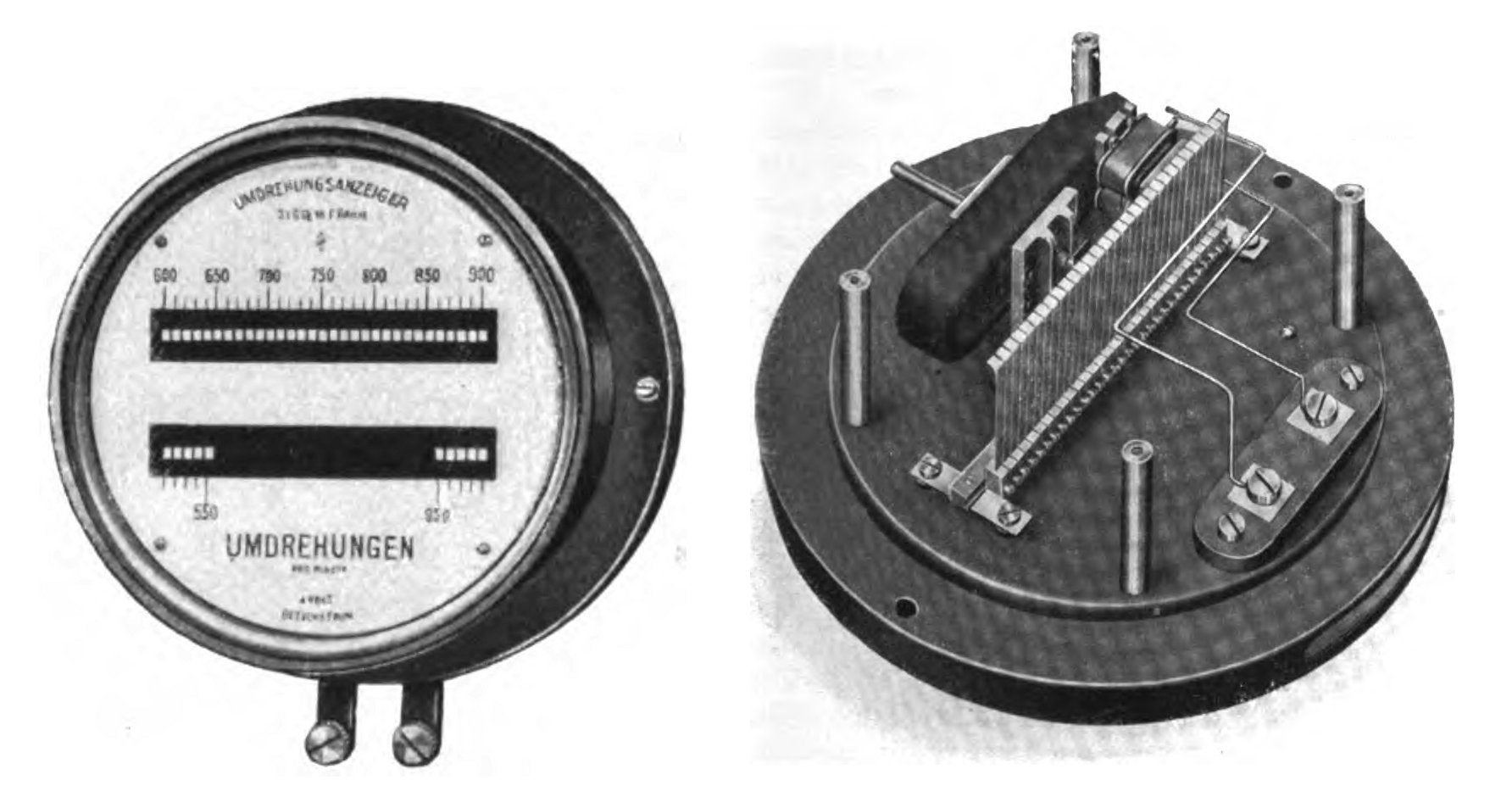
In the bad old days, they used a wonderful mechanical resonant reed meter. This picture is from wikipedia. All the reeds are driven by the waveform, but only one or two at or near the resonant frequency show a large vibration.
Nowadays, one of the easiest ways to get a high resolution frequency reading in a short time is to digitise the waveform, and demodulate it to frequency. That can be done with the soundcard on a PC and a trivial program.
Before the advent of cheap ADCs, they would use a standard frequency counter, perhaps using a PLL in front of it to multiply the frequency by 100 or 1000 to get decent resolution in a short time.
An alternative way to get a fast reading with a standard counter is to do TIC, Time Interval Conversion, where you count your high speed reference for one cycle of the low speed input waveform. This is very easy to implement with any cheap MCU like PIC or Arduino, with its internal hardware counters and fast clocks.
There was yet another way to measure frequency finely, quickly, but its opportunity to shine was squeezed out by the arrival of those cheap ADCs, which made waveform digitisation much more convenient.
-
\$\begingroup\$ Is that your patent? Nice application of sigma-delta theory. \$\endgroup\$ Commented Apr 3, 2022 at 8:38
-
1\$\begingroup\$ @pericynthion Yes. It was being built into one product, that got canned for other unrelated reasons. I then tried to develop it into an FM demodulator, but being sigma delta, we couldn't get more than audio bandwidths out of it. Then 100MHz+ ADCs got affordable and good and the rest is history. But from time to time, an application surfaces where it might be the right technique to make an Arduino into a high speed high resolution counter for cheap. \$\endgroup\$– Neil_UKCommented Apr 3, 2022 at 9:26
A small synchronous motor attached to a gear train — i.e., an electric clock — functions as a cycle counter. By counting the number of cycles in a known interval (established by some other timebase), you can derive the grid frequency to high accuracy:
- 60 cycles in one second (1.6% accuracy)
- 3600 cycles in one minute (0.028% accuracy)
- 216000 cycles in one hour (4.63 ppm accuracy)
- 5184000 cycles in one day (0.193 ppm accuracy)
For protection applications (where small variations of frequency over fractions of a second are important to measure) the frequency can be measured by timing the interval between voltage waveform zero crossings.
In a 50 Hz system, there should be 10 ms between zero crossings.
This method is prone to problems when there are noise, inrush or transient events that cause the timing of a zero crossing to change (or, in the worst case, for a zero crossing to be skipped entirely.)
This was the root cause for a spurious 132kV circuit breaker operation we had at my old workplace. Energizing a transformer, somewhere else on the network, caused a blip in the voltage waveform. The protection relay's frequency measurement algorithm (based on zero crossings) interpreted this blip as an extra zero crossing, causing an error in frequency measurement and thus a spurious trip.
This is one of the methods mentioned in the Schweitzer Engineering Laboratories (SEL) paper linked by @relayman357. SEL is a specialised relay manufacturing company and their content is usually top notch.
The second (new?) approach in the SEL presentation is based on correlating the measured waveform with an ideal sine wave of frequency F, where you sweep through a range of F to find the value that best matches the measured waveform.
Approaches based on Fourier Transform / FFT techniques probably wouldn't be useful, as to detect the sorts of frequency deviations we are interested in (fractions of a Hz over long periods, or multiple Hz over a couple of cycles) too much data would be required to give timely results.
-
\$\begingroup\$ wooow, thank you very much for sharing your experience and for answering my question! \$\endgroup\$ Commented Apr 3, 2022 at 10:11

