2
\$\begingroup\$

I am repairing 8 second-hand microgrid inverters from 2013.
The internal structure is a push-pull sinusoidal current generator. DC input 12 to 28V, 250W. The primary side suffers from a design problem.

5 of them had dead primary mosfets (STB75NF75, Vds max = 75V) in permanent conduction with blown fuses. I looked for the fault and I think that the voltage spikes above 75V are related to the push-pull structure and the leakage inductance. On each branch, there is a snubber and a 58V tvs diode to protect the mosfets. The snubbers are not perfectly tuned to the parasitic elements but they are still quite effective. schematic
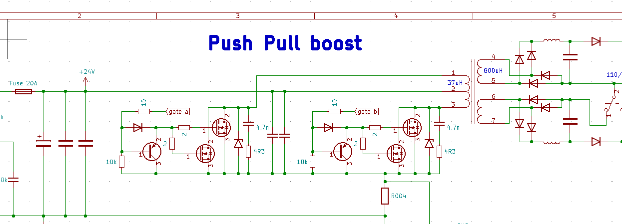
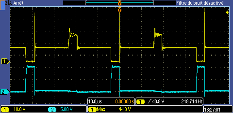
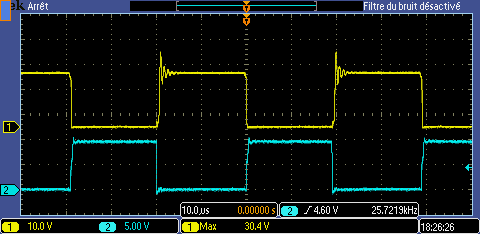
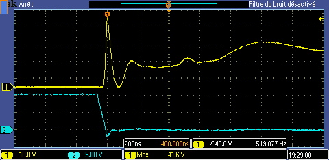
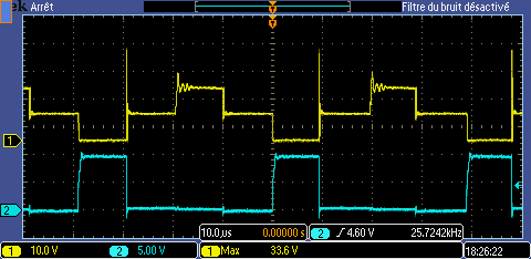
Today I have an inverter that generates large spikes on the mos drain just after the gate off command. However the snubber and diodes are good. This occur only on one branch, not on the other side. I don't understand why I have this. On the other hand, the spikes seem to occur in specific cases. You can see below the appearance of this peak which is almost 4x larger than the input voltage of 12V, at different duty cycles. The load does not affect this peak but the higher the input voltage, the larger the peak. The spikes are more pronounced at lower duty cycles. In yellow, drain voltage. In blue, Vgs.

spikes at 50% dt spikes at 25% dt

As the current setpoint oscillates at 100hz, it is quite difficult to get a constant pickup of the peaks on the oscilloscope. Sometimes the drain voltage is stable.

large dt zoom on spike

On the others micro-inverters I don't have this, or a little spikes on the drain when the other branch start conducting.

I have read that leakage inductance can increase with gap to transformer but here the EE core is well glued. Is it a sign of a too fast Off mosfet switching, or a secondary problem reflected on the primary ?

\$\endgroup\$
5
  • \$\begingroup\$ Alas, the perfidious leakage inductance is also at work in a push-pull converter. No, a gap does not affect the leakage inductance. It does affect the magnetizing inductance but not the leakage term which depends mostly on the winding geometry. It was long time ago demonstrated by Drs. Cuk and Middlebrook. \$\endgroup\$ Commented Apr 6, 2022 at 18:38
  • \$\begingroup\$ Thanks, I understand much better. But then in my case, it would be more a defect of winding on the 2nd arm? \$\endgroup\$
    – Ambroise
    Commented Apr 12, 2022 at 7:29
  • \$\begingroup\$ The best, perhaps, is to compare the primary currents in both legs and check the slopes: any significant difference between the two would indicate something suspicious with the transformer or elsewhere. \$\endgroup\$ Commented Apr 12, 2022 at 19:00
  • \$\begingroup\$ Did you at any point measure the transformer leakage inductance and MOSFET capacitance so you could determine the optimal snubber values? The ringing on your scope plots appears to be under-damped, which suggests the wrong combination of snubber capacitance and resistance. \$\endgroup\$
    – user4574
    Commented Apr 19, 2022 at 17:33
  • \$\begingroup\$ Yes I tried to measure the leakage inductance but I didn't succeed due to lack of material (shorted secondary method). I tried several values of capacitor with a variable resistance of power 100ohms and 10ohms. I found the ideal 10nF 2ohms pair but the resistor (2W) was getting very hot so for the efficiency of the converter I left the snubber in place. \$\endgroup\$
    – Ambroise
    Commented Apr 21, 2022 at 7:51

1 Answer 1

2
\$\begingroup\$

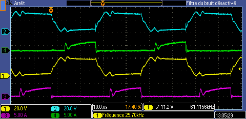
I continued my measurements and also found voltage peaks on the other leg. They do not appear at the same time. Finally, I decided to try to reduce the slew rate at the gate off command by removing the pnp bjt and bypassing the diode on the gate command. After that, no more problems with voltage spikes. The curves are as expected in the theory. However, the edges are still steep enough not to lower the efficiency too much. I also checked that there was not an imbalance between the 2 legs but it is not the case, as shown in this capture (Vd and Id on each leg).

enter image description here

\$\endgroup\$

Your Answer

By clicking “Post Your Answer”, you agree to our terms of service and acknowledge you have read our privacy policy.

Not the answer you're looking for? Browse other questions tagged or ask your own question.