7
\$\begingroup\$

Two optocouplers are connected according to the circuit below. The input voltage across the first optocoupler is a true square wave (3.3 V amplitude). The first optocoupler is an open collector output and the second one is an open collector input.
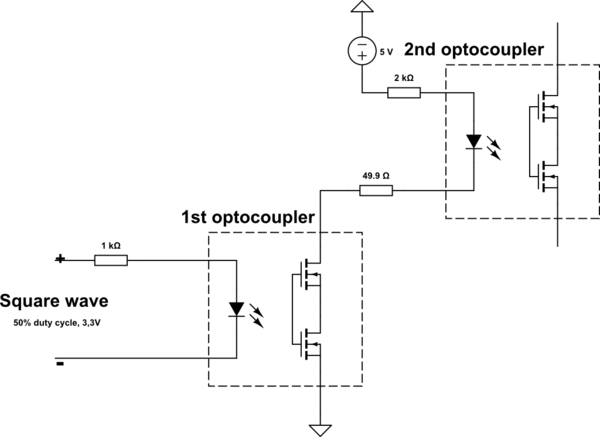
schematic

simulate this circuit – Schematic created using CircuitLab

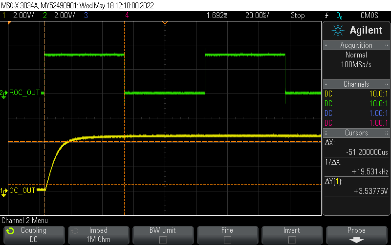
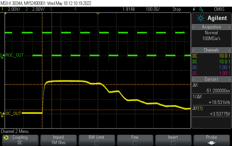
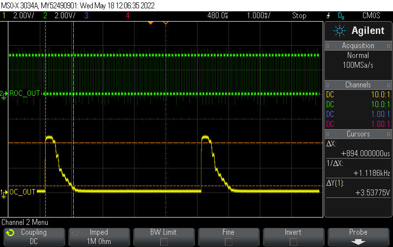
When switching with a low frequency, the signal at the output of the first optocoupler changes according to the input signal (true square wave). But when the frequency goes up, the optocoupler's behavior gets weird. It was expected that at a high frequency, the optocoupler would turn on once and not turn off as long as the input voltage (true square wave) was applied. In fact, switching of the first optocoupler with a frequency less than the frequency of the input signal is observed.

Could you please explain what physical processes cause such behavior of the optocoupler?

On each oscillogram, the top green signal is true square wave input and the bottom yellow one is the voltage at the cathode of the second optocoupler. The optocopulers are PS7122AL-2A-A.

enter image description here

enter image description here

enter image description here

\$\endgroup\$
2
  • 3
    \$\begingroup\$ What do you mean by "open collector input"? \$\endgroup\$
    – The Photon
    Commented May 19, 2022 at 14:29
  • \$\begingroup\$ I understand this is the part of a device that can be driven by an open collector output. \$\endgroup\$
    – Tommazo
    Commented May 20, 2022 at 16:03

2 Answers 2

10
\$\begingroup\$

The PS7122AL-2A-A is not just an optocoupler. It is defined as a SSR or Solid-State Relay.

On page 6, this datasheet states that \$t_{on}\$ is max 1.5ms and \$t_{off}\$ is max 0.2ms. 1/1.5ms = 667Hz, so already this can be seen as a slow device. At the bottom of that page it reads:

The turn-on time and turn-off time are specified as input-pulse width ≥ 10ms. Be aware that when the device operates with an input-pulse width less than 10ms, the turn-on time and turn-off time will increase.

It isn't stated further how much it will increase; however you have found the answer experimentally - it can increase a lot to the point of behaving erratically.

SSR's are intended to switch a load on or off only, infrequently, not PWM them quickly. For that, a real optocoupler (such as an opto-transistor) is needed. The effect you are seeing is likely due to there being many more physical components/circuitry present inside the package than the drawings indicate.

Typically, SSR outputs must deal with relatively high voltages, bi-directional AC, and surge currents. So additional components/circuitry is added to protect the switching devices and facilitate such operation. Those additional components tend to be rather slow-acting, resulting in the strange behavior witnessed.

\$\endgroup\$
1
  • \$\begingroup\$ Thank you! It's become much clearer. \$\endgroup\$
    – Tommazo
    Commented May 20, 2022 at 16:07
4
\$\begingroup\$

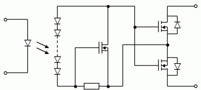
While the internals of a MOSFET based SSR are typically shown as in your circuit, it is a gross simplification of the real circuit. In reality the LED illuminates a separate photocell array which produces the Gate drive voltage, and a discharge circuit removes charge from the FET Gates when the LED is turned off.

Here's a (still simplified!) diagram of the internal circuit of a Panasonic PhotoMOS relay:-

enter image description here

The extra FET normally acts as a current sink to discharge the FET Gates quickly when the photocell array is not illuminated, but is turned off while the output FETs are being turned on to reduce its effect on turn-on time.

The real circuit could be even more complex than shown here, with more components controlling the discharge FET's Gate. At high switching frequencies this circuit could get 'confused', resulting in the behavior you see.

\$\endgroup\$
3
  • \$\begingroup\$ Thank you! I did not even suspect that the internal circuit is so complex. \$\endgroup\$
    – Tommazo
    Commented May 20, 2022 at 16:09
  • \$\begingroup\$ I'm pretty sure the discharge device is usually a JFET, though I think a depletion mode MOSFET would work just as well. \$\endgroup\$
    – Hearth
    Commented May 20, 2022 at 16:25
  • \$\begingroup\$ @Hearth Here's the description of an 'accurate pspice model' from Panasonic that uses a 'level 1 MOSFET model that includes threshold voltage.' panasonicelec.wordpress.com/2011/07/07/… Might be worth trying this model to see what it does! \$\endgroup\$ Commented May 20, 2022 at 22:02

Your Answer

By clicking “Post Your Answer”, you agree to our terms of service and acknowledge you have read our privacy policy.

Not the answer you're looking for? Browse other questions tagged or ask your own question.