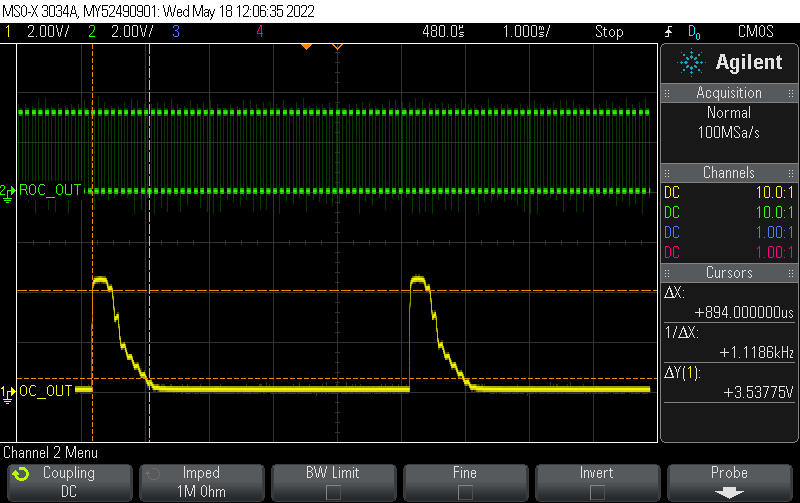
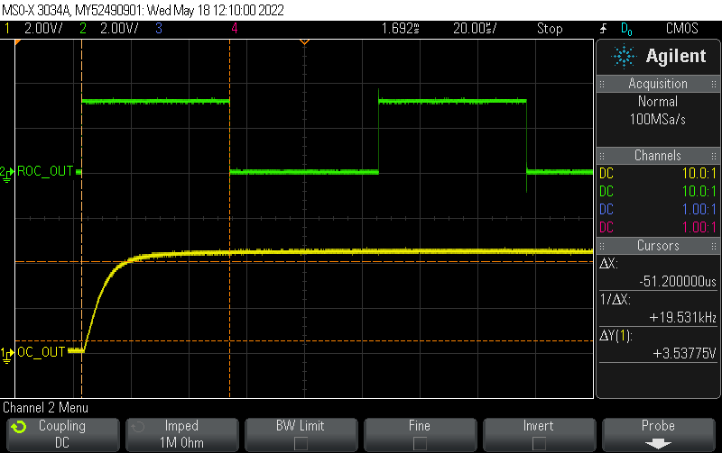
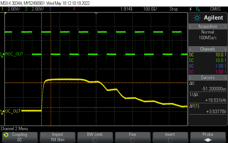
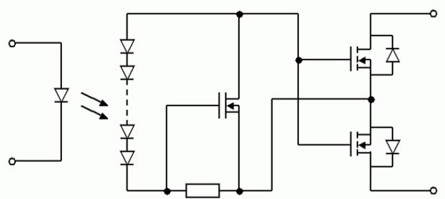
Two optocouplers are connected according to the circuit below. The input voltage across the first optocoupler is a true square wave (3.3 V amplitude). The first optocoupler is an open collector output and the second one is an open collector input.
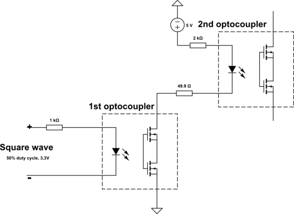
simulate this circuit – Schematic created using CircuitLab
When switching with a low frequency, the signal at the output of the first optocoupler changes according to the input signal (true square wave). But when the frequency goes up, the optocoupler's behavior gets weird. It was expected that at a high frequency, the optocoupler would turn on once and not turn off as long as the input voltage (true square wave) was applied. In fact, switching of the first optocoupler with a frequency less than the frequency of the input signal is observed.
Could you please explain what physical processes cause such behavior of the optocoupler?
On each oscillogram, the top green signal is true square wave input and the bottom yellow one is the voltage at the cathode of the second optocoupler. The optocopulers are PS7122AL-2A-A.

