6
\$\begingroup\$

I would like to build a small circuit to measure with my oscilloscope the power emitted by the 5.8GHz video transmitters mounted on my drones. On searching, I found this answer.

The question recommends using a 50 ohm dummy resistive load.

Why was that value chosen? Is it random or can the optimal value be calculated?

Personally I will have to measure signals with power lower than one watt.

To have precise measurements and avoid damaging the video transmitter, is that 50 ohm resistor sufficient, or is a more complex circuit necessary as shown here?

\$\endgroup\$
4
  • 2
    \$\begingroup\$ 50 ohms is a standard characteristic impedance value. As for why... the answer is part technical, part historical. It's summarised nicely here. \$\endgroup\$
    – Polynomial
    Commented Mar 5, 2023 at 0:50
  • 1
    \$\begingroup\$ Do you have an oscilloscope capable of measuring 5.8 GHz? \$\endgroup\$
    – GodJihyo
    Commented Mar 5, 2023 at 1:26
  • 1
    \$\begingroup\$ BTW, at that frequency, attaching the probes may be difficult, particularly if there is no antenna jack on the transmitter, and lead length is critical. Standing waves would be an issue. \$\endgroup\$ Commented Mar 5, 2023 at 2:03
  • \$\begingroup\$ @GodJihyo My oscilloscope is a HANMATEK DOS1102 with 1GSa/s. Surely he will have problems measuring such high frequencies, but as an alternative I have an old multimeter paid for 5 euros. which of the die tools is better to use? \$\endgroup\$
    – Pinguto
    Commented Mar 5, 2023 at 3:24

2 Answers 2

10
\$\begingroup\$

You need to use a power sensor.

A rudimentary one, yet quite adequate for your use, takes just a couple of components.

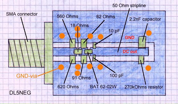
An example design by Herbert Dingfelder – DL5NEG is pictured below. I've also drawn a schematic below, other pictures are Herbert's.

Layout of a simple power sensor

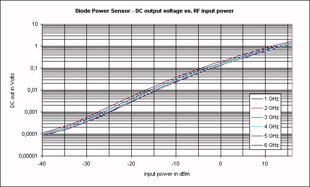
The output voltage vs input power response:

Output voltage vs input power response of a simple power sensor

schematic

simulate this circuit – Schematic created using CircuitLab

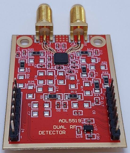
A higher accuracy integrated sensor - probably a bit overkill for your use - could be for example this one built and offered for sale by SV1AFN. Picture from the listing:

ADL5519 Dual Channel RF Power Meter for ARDUINO or other MCU 1 MHZ-10 GHZ SV1AFN

You'll need an Arduino to connect to it to read out the power.

The maximum input power of that one, for reasonable accuracy, is around 3mW or -5dBm. To measure higher power, you'll need an attenuator connected in-line.

\$\endgroup\$
8
\$\begingroup\$

You're not going to be able to directly measure a 5.8 GHz signal with the oscilloscope you have, it's rated bandwidth is 110 MHz. A multimeter is going to be even worse, probably less than 20 KHz.

Measurements at frequencies that high require special equipment and techniques, even very short wires can be a significant fraction of a wavelength.

What you need is an RF power meter designed for that frequency range (an internet search should turn up meters made for RC hobbyists that will cover the 5.8 GHz) or something like a directional coupler and RF detector rated for that range. This will basically rectify the RF and output a DC voltage that you can measure with a DMM or scope.

You can check this video to get some ideas about how to make measurements at this frequency.

\$\endgroup\$
1
  • \$\begingroup\$ AFAICT a directional coupler (if I'm thinking of the same interpretation that you are) is a mostly linear device that can help with power sensing in certain scenarios (i.e. by sampling a small and well-controlled proportion of power), but won't do rectification or provide a measurable signal suitable for an oscilloscope. \$\endgroup\$
    – nanofarad
    Commented Mar 5, 2023 at 18:42

Your Answer

By clicking “Post Your Answer”, you agree to our terms of service and acknowledge you have read our privacy policy.

Not the answer you're looking for? Browse other questions tagged or ask your own question.