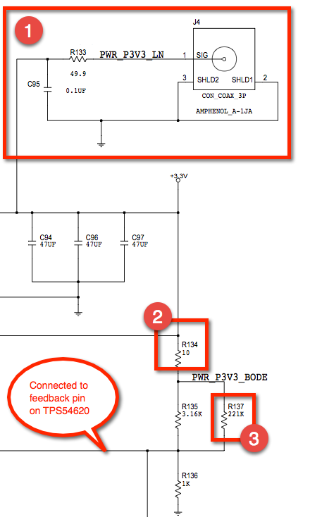
I recently came across this circuit for measuring the output of a TPS54620 switching regulator (12V->3.3V). I'm not a power engineer, so I'd like some help understanding the parts in red boxes (presumably used by the power engineer to measure the power supply?)

1) Is this Hirose U.FL coax connection (J4) used for measuring the output ripple and/or noise on the regulated 3.3V output? I think the 49.9 ohm resistor is used to provide a 50-ohm source impedance to match a 50-ohm coax cable, which is presumably terminated via a 50-ohm BNC pass-through (or the 50-ohm setting on a scope). Is 49.9-ohm used instead of 50-ohm to ensure that the resistance is precise to within 0.1-ohm? (just curious why you'd use a 49.9 ohm...)
If the designer was just concerned with ripple/noise, why wouldn't they add a DC blocking capacitor in series before the 49.9 ohm resistor? Since there is no DC blocking, this presents a 100-ohm DC load (49.9-ohm + 50-ohm), which results in a static current draw. For 3.3V output, this is probably ok (3.3V * (3.3V / 100-ohm) = 0.1W), but if the output was 12V, you'd get 12V * (12V / 100-ohm) = 1.44W, which I think is too much power for the 50-ohm input on my scope. Do people normally put some kind of DC block inline with the coax cable? What is the best practice for putting an onboard coax connection like this? What tests is this connection typically used for?
2) I believe R134 (the 10-ohm resistor) is for loop stability measurements (see http://www.tij.co.jp/jp/lit/an/snva364a/snva364a.pdf) TI recommends adding a 20-ohm resistor into the feedback loop of the power supply for bode measurements, and I think the 10-ohm resistor is for the same purpose here. Is this correct? Any other reason for this resistor?
3) Why have another large resistance (R137) in parallel with the upper half of the feedback divider? The TI reference design uses 31.6k/10k resistors in the feedback loop, so 3.16k/1k seem like they should be the correct value without R137. I'm not sure why you'd want this resistor?
