1
\$\begingroup\$

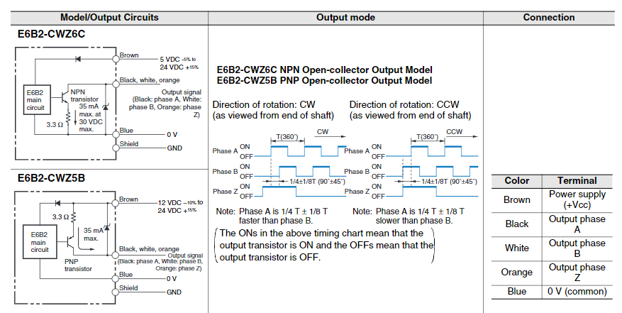
I have an encoder; the circuit is in the image below:

Datasheet

The one that I’m interested in is the PNP one. I want to use a 0-5 V digital voltage, the datasheet says this:

  1. Applied voltage: 30 VDC max.
  2. Source current: 35 mA max
  3. Residual voltage: 0.4 V max. (at source current of 35 mA)

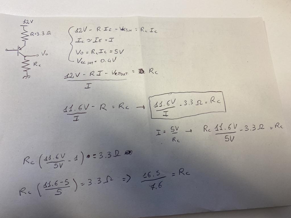
By my calculations using Kirchhoff's law I can't obtain 5 V because of the 35 mA max; the pull-down resistor should be very low, because the emitter resistor is very low. Am I missing something? How can I dimension the resistor correctly?

enter image description here

This is the calculation that I made, what is wrong?

\$\endgroup\$
0

2 Answers 2

2
\$\begingroup\$

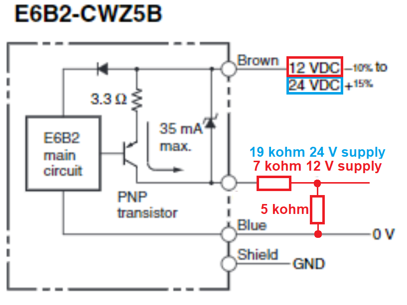
It says the maximum current is 35 mA and, that would mean the transistor might be on-the-cusp of failing so, choose a more reasonable current like 5 mA and calculate a resistor value that's 1 kΩ. You could probably go as low as 1 mA with a 5 kΩ resistor.

But, there is a minor problem pointed out by @periblepsis; the minimum supply voltage for this device is 12 volts so, in effect, you'll have to use two resistors and form a potential divider like this: -

enter image description here

\$\endgroup\$
8
  • 1
    \$\begingroup\$ The transistor is operating as a switch so, it'll push the current defined by the resistor and the power supply. Use a 5 volt supply is my recommendation and it's very easy. OK upper logic level might end up being about 4.8 volts but that's fine for logic. \$\endgroup\$
    – Andy aka
    Commented Apr 5, 2023 at 17:04
  • 1
    \$\begingroup\$ @Andyaka The datasheet appears to specify +12 to +24 for the emitter (and 3.3 Ohm) end of the PNP. Elsewhere on the datasheet, for other devices, they do allow +5 V. But not in this case, for the specific E6B2-CWZ5B device. How do you read it? \$\endgroup\$ Commented Apr 5, 2023 at 19:32
  • 1
    \$\begingroup\$ @periblepsis yes you are right. Good spot. It needs a potential divider to produce 0/5 volts from a 12 volt supply. \$\endgroup\$
    – Andy aka
    Commented Apr 5, 2023 at 20:04
  • 1
    \$\begingroup\$ ok now its clear, so my calc were not wrong, i just had to use a voltage divider to obtain my voltage without burning the transistor \$\endgroup\$ Commented Apr 5, 2023 at 20:14
  • 1
    \$\begingroup\$ @SergioPiccione correct and sorry for being late in realizing it couldn't run from 5 volts. \$\endgroup\$
    – Andy aka
    Commented Apr 5, 2023 at 20:35
2
\$\begingroup\$

The one that I’m interested in is the PNP one. I want to use a 0-5 V digital voltage, the datasheet says this:

Applied voltage: 30 VDC max.
Source current: 35 mA max
Residual voltage: 0.4 V max. (at source current of 35 mA)

I think you may have purchased the wrong encoder (or are contemplating such), if you are stuck with a \$5\:\text{V}\$ source voltage. Here's why:

enter image description here

Note that in the specific case of the only device they make as PNP, that they specify \$12\:\text{V}\to 24\:\text{V}\$, which appears to me to exclude \$5\:\text{V}\$. Strengthened also by the fact that the other three versions they make do support \$5\:\text{V}\$.

\$\endgroup\$
6
  • \$\begingroup\$ yes i know i buyed the wrong one, too late for that, i was asking if i could fix that, so i have to put a voltage divider, i was thinking to a op amp inverter with negative reaction \$\endgroup\$ Commented Apr 5, 2023 at 20:07
  • \$\begingroup\$ @SergioPiccione Then you will need a 12 V to 24 V supply. No getting around that, without deciding to first ignore the specifications and then perform some testing on the device to see if it can be made to work on 5 V. Do you have access to the appropriate voltage supply? Or only to 5 V? \$\endgroup\$ Commented Apr 5, 2023 at 20:08
  • \$\begingroup\$ nono i have access to the correct voltage supply, just interested in the output \$\endgroup\$ Commented Apr 5, 2023 at 20:09
  • 1
    \$\begingroup\$ @SergioPiccione Oh. Then Andy's suggestion about a divider could work. Or a different circuit using another BJT. Personally, I'd use an added BJT circuit. But it can be made to work with dividers. \$\endgroup\$ Commented Apr 5, 2023 at 20:10
  • 1
    \$\begingroup\$ @SergioPiccione The resistors mentioned by Andy are fine. You 'could' add a BJT (or two or three, etc.) The extra BJT allows me another degree of flexibility and the possibility to protect your I/O pin from a single part failure (short, for example.) But you've not mentioned anything to suggest a need for that. I think the divider will be fine. Just don't use a screwdriver and accidentally short out the upper resistor in the divider! \$\endgroup\$ Commented Apr 5, 2023 at 21:48

Your Answer

By clicking “Post Your Answer”, you agree to our terms of service and acknowledge you have read our privacy policy.

Not the answer you're looking for? Browse other questions tagged or ask your own question.