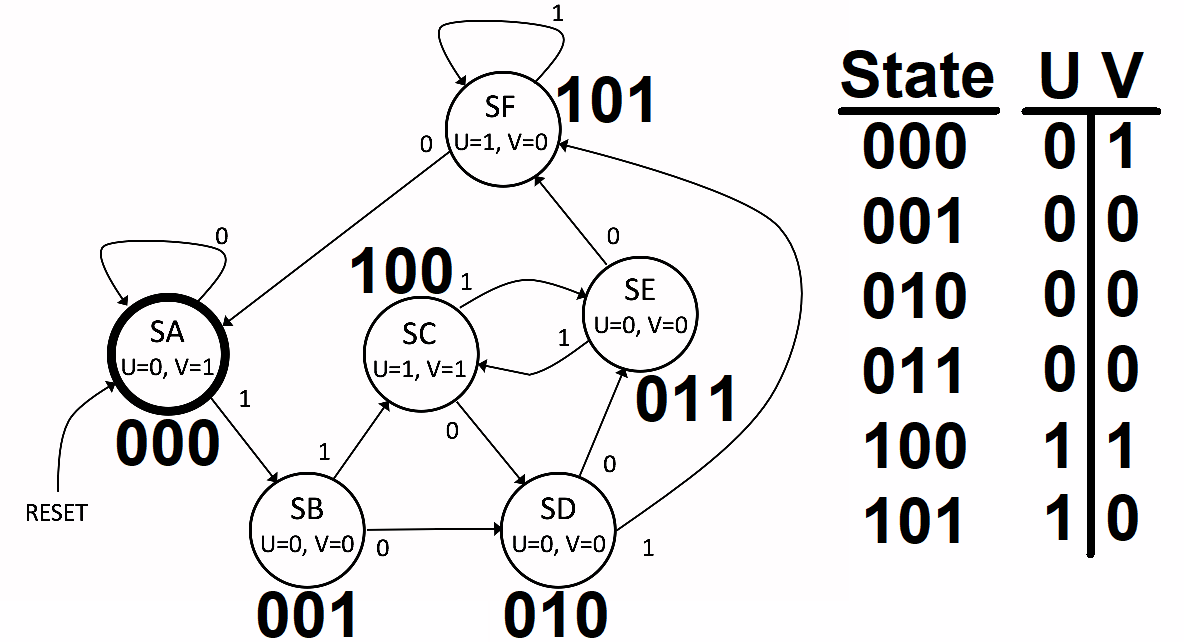
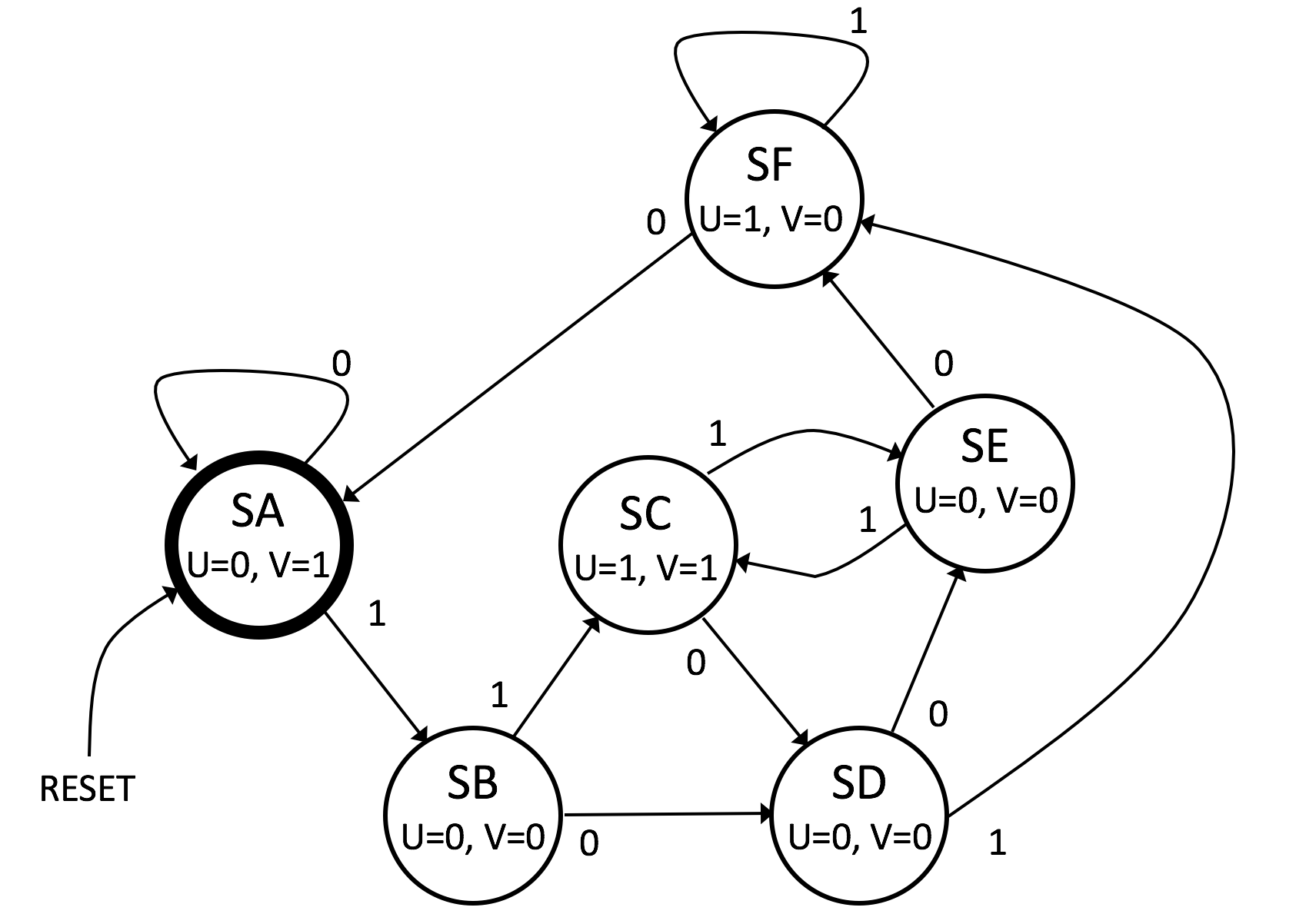
Let's start by assigning state numbers to each state:

My reasoning here is that \$U\$ is just a copy of the most significant DFF. That makes \$U\$ easy to produce. Next, I decided that \$V=1\$ when both of the less significant DFFs are zero. That's also easy to produce.
From here it is now possible to create a table:
$$\begin{array}{c|c|c}
\text{State} & \text{IN} & \text{New State}\\\hline\\
{\begin{smallmatrix}\begin{array}{ccc}
Q_C & Q_B & Q_A\\
\\
0&0&0\\
0&0&0\\
0&0&1\\
0&0&1\\
0&1&0\\
0&1&0\\
0&1&1\\
0&1&1\\
1&0&0\\
1&0&0\\
1&0&1\\
1&0&1\\
\\
1&1&0\\
1&1&0\\
1&1&1\\
1&1&1
\end{array}\end{smallmatrix}} &
{\begin{smallmatrix}\begin{array}{c}
\\ \text{ }\\0\\1\\0\\1\\0\\1\\0\\1\\0\\1\\0\\1\\\\0\\1\\0\\1
\end{array}\end{smallmatrix}}
&
{\begin{smallmatrix}\begin{array}{ccc}
Q_C & Q_B & Q_A\\
\\
0&0&0\\
0&0&1\\
0&1&0\\
1&0&0\\
0&1&1\\
1&0&1\\
1&0&1\\
1&0&0\\
0&1&0\\
0&1&1\\
0&0&0\\
1&0&1\\
\\
x&x&x\\
x&x&x\\
x&x&x\\
x&x&x
\end{array}\end{smallmatrix}}
\end{array}$$
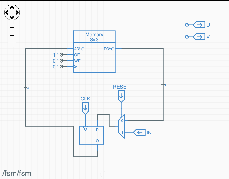
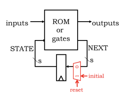
That table should be very easy to stick into a ROM along with the associated \$U\$ and \$V\$ values. You could either latch them from the ROM output at the time of the clock-driven state transition or else derive them from the current address presented at the ROM address bus prior to the next clock.
Alternately, you avoid the ROM and instead just produce the Karnaugh maps:
$$\begin{array}{rl}
\begin{smallmatrix}\begin{array}{r|cccc}
Q_C\text{ }D&\overline{Q_A}\:\overline{IN}&\overline{Q_A}\: IN&Q_A \:IN&Q_A \:\overline{IN}\\
\hline
\overline{Q_C}\:\overline{Q_B}&0&0&1&0\\
\overline{Q_C}\:Q_B&0&1&1&1\\
Q_C\:Q_B&x&x&x&x\\
Q_C\:\overline{Q_B}&0&0&1&0
\end{array}\end{smallmatrix}
&
\begin{smallmatrix}\begin{array}{r|cccc}
Q_B\text{ }D&\overline{Q_A}\:\overline{IN}&\overline{Q_A}\: IN&Q_A \:IN&Q_A \:\overline{IN}\\
\hline
\overline{Q_C}\:\overline{Q_B}&0&0&0&1\\
\overline{Q_C}\:Q_B&1&0&0&0\\
Q_C\:Q_B&x&x&x&x\\
Q_C\:\overline{Q_B}&1&1&0&0
\end{array}\end{smallmatrix}\\\\
\begin{smallmatrix}\begin{array}{r|cccc}
Q_A\text{ }D&\overline{Q_A}\:\overline{IN}&\overline{Q_A}\: IN&Q_A \:IN&Q_A \:\overline{IN}\\
\hline
\overline{Q_C}\:\overline{Q_B}&0&1&0&0\\
\overline{Q_C}\:Q_B&1&1&0&1\\
Q_C\:Q_B&x&x&x&x\\
Q_C\:\overline{Q_B}&0&1&1&0
\end{array}\end{smallmatrix}
\end{array}$$
And work out the logic required for that from the usual means of minimizing logic from those tables.


