1
\$\begingroup\$

I'm working on a problem where I'm trying to design a digital logic circuit (sequential circuit?) to produce output Y given input A:

enter image description here

So the goal is to produce one pulse for every 5 input pulses.

What I've got so far is to use a 3-bit counter, and then feed their outputs into an AND gate like below (everything is negative edge-triggered): enter image description here
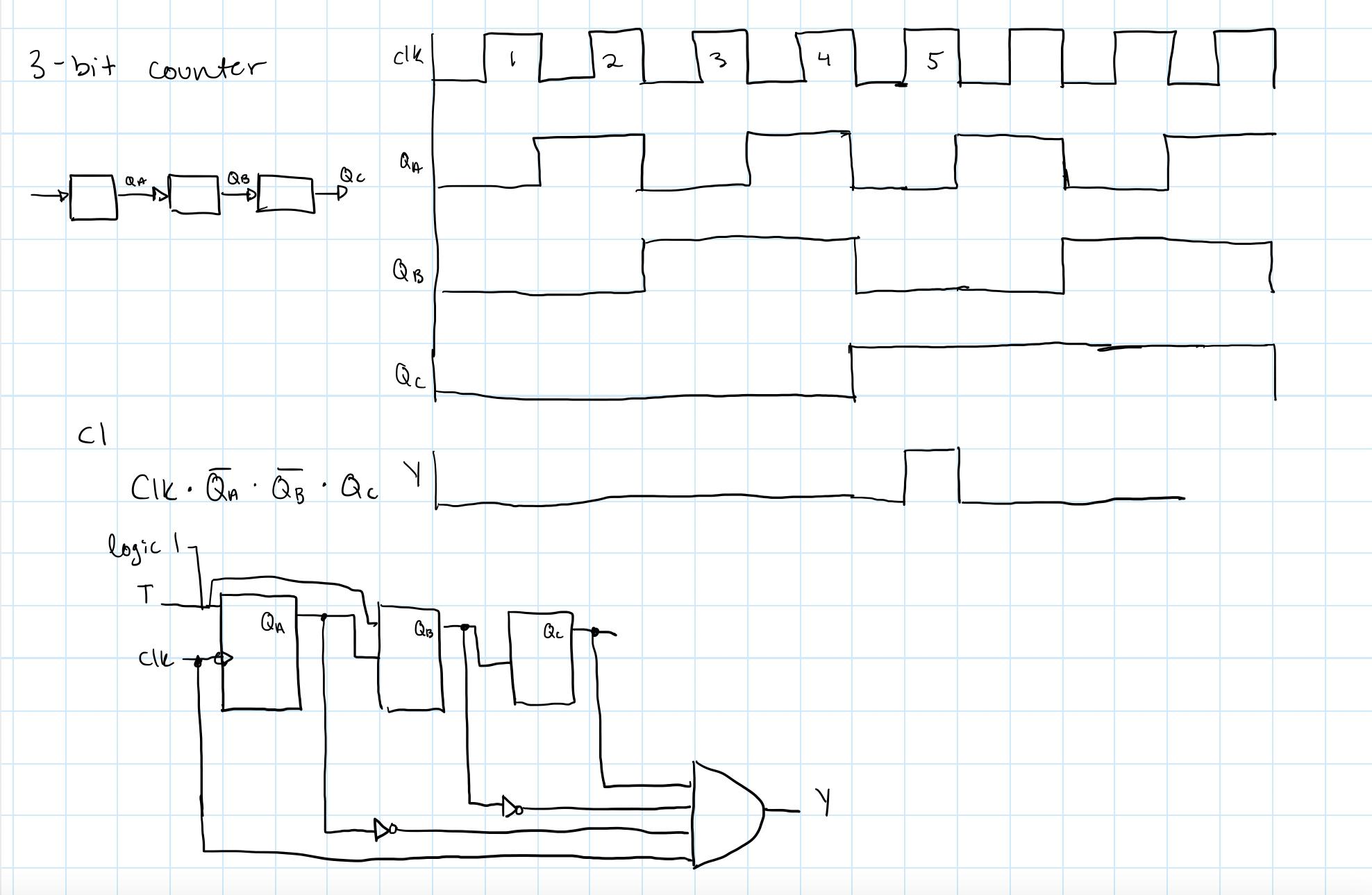
My thought was that the output should only be high when (CLK and Qc and NOT Qb and NOT Qa) is high. Does this make sense? I don't have a simulink license so I'm not sure how to check this. Is there a better/simpler way to do this/am I missing something? Any pointers or guidance are appreciated. Thanks!

\$\endgroup\$
11
  • 1
    \$\begingroup\$ draw the timing diagram to the second output pulse \$\endgroup\$
    – jsotola
    Commented Oct 27, 2021 at 15:48
  • 1
    \$\begingroup\$ You will need to reset the counter; using JK flip flops can make this much simpler. \$\endgroup\$ Commented Oct 27, 2021 at 15:49
  • 1
    \$\begingroup\$ With asynchronous counter, the combination of Q-s will see glitch due to the propagation delay. \$\endgroup\$
    – jay
    Commented Oct 27, 2021 at 16:04
  • \$\begingroup\$ Look for 'finite state machines using JK flip flops'. From a quick look, I can make a synchronous solution using 3 JK devices and 2 2-input AND gates. \$\endgroup\$ Commented Oct 27, 2021 at 16:09
  • 3
    \$\begingroup\$ There are plenty of free simulators. For example, Logisim seems to work well. \$\endgroup\$
    – Dave Tweed
    Commented Oct 27, 2021 at 16:28

2 Answers 2

1
\$\begingroup\$

First of all, my advice would be to use a free logic simulator such as Logisim, which I myself mostly use.

Second, now about your circuit. It is perfectly doable with D flip flops only: three of them are used to count 0-4. Counting state 0, the counter has five states. Finally, a fourth flip-flop whose clock is driven by the main clock delays the reset by once cycle, which effectively restarts the counter section.

enter image description here

Be aware however, that this implementation may not work at high frequencies. If your goal requires high speed then use JK flip-flops to make it into a synchronous counter.

\$\endgroup\$
1
\$\begingroup\$

Ali: Your circuit is a good first effort. All it needs is a way to reset the counter after the desired output pulse ends. But it can be simplified.

Based on your own timing diagram (thanks for that), because the counter always counts up, you can ignore some of the outputs. You can see that as long as Qc is low, Qa and Qb can be ignored. Then, when Qc is high, the desired output signal equals the next clock pulse. Thus, you can reduce the 4-input AND gate to a 2-input AND gate (Qc AND clk). This essentially is what is going on in the circuit by Borg.

The advantage is that his circuit includes a way to reset the counter, while yours still needs it to be added in. This can be done with a differentiator that uses the trailing edge of the Y signal to pulse the counter's Reset input.

Another way to do this is with a CD4017 Johnson counter plus one 2-input AND gate (or two diodes). As with the Borg circuit, one of the 4017 outputs is used to reset the counter so no more parts are needed for that.

\$\endgroup\$

Your Answer

By clicking “Post Your Answer”, you agree to our terms of service and acknowledge you have read our privacy policy.

Not the answer you're looking for? Browse other questions tagged or ask your own question.