1
\$\begingroup\$

I am tinkering with logic gates preparing for an exam and came across a question that states the following

Construct a common bus system for six registers where each register has five bits.

the expression I got from the truth table was

S2'S1'S0'D0 + S2'S1'S0D1 + S2'S1S0'D2 + S2'S1S0D3 + S2S1'S0'D4

where ' is the complement

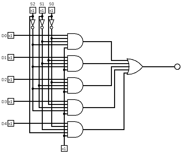
the circuit that I constructed looks like

5to1Mux

Assuming the design is right, my question is that I have 6 registers and this design relies on one of the (D0-D4) being 1 and the rest is not important. How can this be used to reference 6 registers? What am I missing because I can't grasp the idea behind it?

The registers and their bits

  • first 10000
  • second 01000
  • third 00100
  • fourth 00010
  • fifth 00001

As far as I can tell there is not sixth register with only one bit being 1

  • bottom input bit is the enable
  • top three bits are the selectors
  • left 5 bits are the register bits
\$\endgroup\$
1
  • \$\begingroup\$ Observations: 1) buses have multiple participants, I expect multiple signal sources for a single line (or pair of lines) in at least one direction. 2) registers have inputs, too. 3) six registers, not five. \$\endgroup\$
    – greybeard
    Commented Jun 8, 2023 at 20:31

1 Answer 1

1
\$\begingroup\$

Here is how I interpret the exam question. You want the bus to select 1 of the 6 registers. Conceptually, this is a 6:1 mux, where the mux output is a 5-bit data bus. There are 6 data inputs to the mux, each of which is 5 bits wide. You have 6 5-bit registers, for a total of 30 register bits.

The 6:1 mux requires 3 select bits, as you have chosen.

The diagram you created represents one data bit from each of 5 registers. D0 is from the 1st register, D1 is from the 2nd, ... D4 is from the 5th. Now you need to add a 6th term: S2S1'S0D5. Your OR gate needs a 6th input, and you need to add a 6th AND gate for D5.

S2'S1'S0'D0 + S2'S1'S0D1 + S2'S1S0'D2 + S2'S1S0D3 + S2S1'S0'D4 + S2S1'S0D5

To handle all 5 bits of the output, you need to replicate your diagram 5 times.

Since you have 6 registers, you need D5 to be a bit from the 6th register.

\$\endgroup\$
4
  • \$\begingroup\$ but if I add D5 this would result in a 6-bit register which does not match the question description of 5-bit register \$\endgroup\$ Commented Jun 8, 2023 at 20:54
  • 1
    \$\begingroup\$ @WeedCookie: Re-read my answer carefully. D5 is not a 6-bit register. D5 is one bit in the 6th register. You have a total of 30 data bits: 5 bits each in 6 registers. D0, D1, etc. are bits in different registers. \$\endgroup\$
    – toolic
    Commented Jun 8, 2023 at 20:58
  • \$\begingroup\$ If I understood your explaination correctly this means that I have to follow these equations Number of multiplexers needed = Number of bits in each register Number of inputs in each multiplexers needed = Total Number of registers. resulting in 5 multiplexers each having 6 inputs and a common bus that has 5 output lines, right? \$\endgroup\$ Commented Jun 8, 2023 at 21:06
  • \$\begingroup\$ @WeedCookie; Yes! Exactly! \$\endgroup\$
    – toolic
    Commented Jun 8, 2023 at 21:09

Your Answer

By clicking “Post Your Answer”, you agree to our terms of service and acknowledge you have read our privacy policy.

Not the answer you're looking for? Browse other questions tagged or ask your own question.