0
\$\begingroup\$

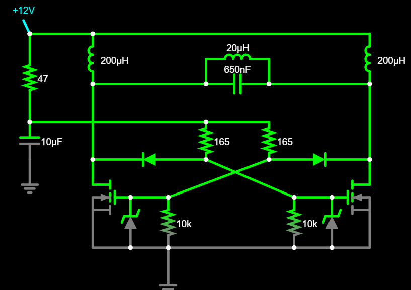
I am trying to put together the ZVS circuit from this website https://www.electroboom.com/?p=1198, however I can not seem to get the circuit to work in a simulation Falstad Circuit, I have already built the circuit minus the inductors and LC tank. and I want to change the circuit to get a lower resonance current.

fortunately I have had a lot of help with working this out on a previous question! However I am not sure how to calculate the voltage going across the tank circuit.

the circuit in falstad

If someone could show me what Ive done wrong on the falstad simulation for it not to be working with the original values , and then could point me in the right direction for working out the voltage across the LC tank that would be fantastic! (I know that the lc tank and the 2 200uh inductors form a loop of total 0 v using KVL and that V = L di/dt, which if i knew the current I could intergrate to solve for v, however I dont know what the current is either.)

\$\endgroup\$
5
  • \$\begingroup\$ while artistically interesting, the fact that this schematic is very disorderly drawn (connections should never have other than multiple-of-90° angles) probably hides a mistake you made while drawing. Wild guess: the two 200µH inductors have been placed on top of a connection and thus are completely useless. Please properly redraw your schematic and make sure only the connections you intend to be there are actually present. \$\endgroup\$ Commented Jul 4, 2023 at 16:15
  • \$\begingroup\$ How does this look? tinyurl.com/24ezgldk \$\endgroup\$
    – Bren
    Commented Jul 4, 2023 at 16:22
  • \$\begingroup\$ I don't know (or at all trust) Falstad, but in general in SPICE simulation this kind of perfectly symmetrical circuit may need a "kick" to get it going. Otherwise it can sit forever like a knife balanced on edge, a mathematical possibility but not a real likelihood. If it sits with one transistor on and the other off (which is a possibility) the 'on' MOSFET and the inductor will see a lot of current and probably one or both will be killed. \$\endgroup\$ Commented Jul 4, 2023 at 16:32
  • 1
    \$\begingroup\$ @SpehroPefhany aha! it starts working if I take one of the inductors out then put it back in in the middle of the simulation - thanks! \$\endgroup\$
    – Bren
    Commented Jul 4, 2023 at 16:35
  • \$\begingroup\$ @Bren Okay, added as an answer. \$\endgroup\$ Commented Jul 4, 2023 at 16:43

1 Answer 1

1
\$\begingroup\$

In general in SPICE simulation this kind of perfectly symmetrical circuit may need a "kick" to get it going. Otherwise it can sit forever like a knife balanced on edge, a mathematical possibility but not a real likelihood.

If you can switch (open or short) one of the components you may be able to kick it into operation in your simulation. In reality leaving the circuit in that incomplete state for more than a very short time could cause failure since the inductors will have very low DC resistance and the MOSFETs can conduct a lot of current.

\$\endgroup\$
2
  • \$\begingroup\$ You can also sometimes change the value of one of the components to create an imbalance and make it oscillate. \$\endgroup\$
    – PStechPaul
    Commented Jul 4, 2023 at 17:14
  • \$\begingroup\$ Yes, especially if you force the power supply to come up relatively suddenly at the start of the simulation, rather than letting the simulator find a starting state. \$\endgroup\$ Commented Jul 4, 2023 at 18:27

Your Answer

By clicking “Post Your Answer”, you agree to our terms of service and acknowledge you have read our privacy policy.

Not the answer you're looking for? Browse other questions tagged or ask your own question.