1
\$\begingroup\$

I'm asking this question again because I think my first attempt may have been a little confusing.

My confusion is stemming from how lowering the resistance leads to lower IR drop.

I have a simple circuit I've drawn below where we have a voltage supply in series with a resistor (used to model the resistance of the lines leading up to the CPU blocks) and 2 CPU blocks (just as an example.)

Let's say the supply voltage is 5 V, that would mean we have I = V/R = 5 / 4k = 1.25 mA of current flowing through the circuit. This would lead to a voltage drop of V = I * R = 1.25 mA * 2kOhms = 2.5 V through the first resistor causing CPU block 1 to see a voltage of 2.5 V and then the same drop through the second resistor causing the second CPU block to see 0 V.

Now let's say we reduce the resistance to lower the IR drop (let's assume we lower both resistors to 1k ohms,) we'd now have I = V/R = 5/2k = 2.5 mA of current flowing through the circuit which would cause a potential drop of 2.5 mA * 1K = 2.5 V through the first resistor and the same through the second resistor, so both CPU blocks see the same voltage.

How did lowering the resistance cause the IR drop to go down? Lowering the resistance simply increases the current according to Ohm's law, so I'm a little confused.

enter image description here

\$\endgroup\$
1
  • \$\begingroup\$ If those blocks are modern CPU or logic, they're probably something like Mega ohms in parallel with a few picofarads of capacitance. Adding those elements into your diagram will probably make it more obvious why lowering the resistance of the wires has a negligible effect on current. \$\endgroup\$ Commented Nov 4, 2023 at 15:03

4 Answers 4

2
\$\begingroup\$

So, if the resistors are the only 2 components in your circuit (except the power source), then you will always have the total IR drop equal to the power source.

Example: You have a 5V battery and 2 1k resistors. Since the positive side of the battery is 5V and the negative is 0V (if we assume that GND is on the negative side, but that does not really matter), then both resistors together will drop 5V, no matter what (assuming the cables do no have any measurable resistance).

You have some additional components in your circuit, the "CPU blocks". These blocks will have some internal resistance as well, causing an "IR" drop too. You need to take that into account when calculating the current flowing through the circuit.

Usually, complex circuits do not have a well-defined resistance, which means that you have to look in the datasheet to see how much current they are sinking, then use that current to calculate the drop over the resistors.

Example: You have one resistor in series with an LED. You know (from the datasheet) that the LED has a voltage drop of 2V while sinking 10mA. Using these numbers, we know that we want 10mA to flow through the resistor too. This means that in order for the circuit to work as intended, the resistor must have a voltage drop of 5-2 = 3V, with 10mA flowing through. So, you have to use a 3V/10mA = 300Ohm resistor to get the desired behaviour.

Does that make sense?

\$\endgroup\$
7
  • \$\begingroup\$ Ine way to understand that resistors have a voltage drop equal to100% f the supplied voltage is to disconnect them from the GND and measure the voltage with a multi meter. Even 1M would show 5V. This is because no energy is consumed. Once you connect a load, the voltage is reduced accordingly. \$\endgroup\$
    – Fredled
    Commented Nov 3, 2023 at 23:56
  • 1
    \$\begingroup\$ @Fredled Not sure what your point is, but if you disconnect the resistors from GND, you will measure 0V across them.. you need a closed loop for any voltage drop to occur \$\endgroup\$
    – Noxet
    Commented Nov 4, 2023 at 13:09
  • \$\begingroup\$ The closed loop is implemented by the two multi meter probes. (The red one on the resistor output and the black on GND.) \$\endgroup\$
    – Fredled
    Commented Nov 4, 2023 at 21:33
  • \$\begingroup\$ @Fredled But now you have created a voltage divider with the multimeter.. You would not (in any case besides when the resistor is 0 Ohms) read 5 V. I fail to see the point here tbh \$\endgroup\$
    – Noxet
    Commented Nov 5, 2023 at 23:45
  • \$\begingroup\$ Sure. But the dividing effet of the multi-meter is négligeable, and it's not difficult to take into account this difference. Multi meters are designed to show the most accurate result. Else it would be impossible to work with them on electronic circuits. \$\endgroup\$
    – Fredled
    Commented Nov 5, 2023 at 23:51
1
\$\begingroup\$

Often when referring to reducing resistance to reduce an IR voltage drop it relates to undesirable resistance in series with other components.

An example would be a high power device on a PCB assembly that may require a high current, possibly a servo motor, a voltage regulator, a complex CPU chip, several LEDs, etc. If the power traces to this device are routed using thin PCB traces there could be a significant series resistance in the traces. With a high current flow and high series resistance these traces could cause an undesirable voltage drop once the trace reaches the high power component. If these same traces were increased in width the series resistance would be reduced thereby reducing the voltage drop (IR loss). The current into the device may be increased as a result, however the more important result is that the full intended voltage (and power) is being delivered to the device more efficiently.

With some PCB software you can actually find the expected resistance of a copper trace on a PCB (the software uses the trace length, width, and thickness). Then by knowing the expected current along the trace you could calculate the potential IR voltage loss.

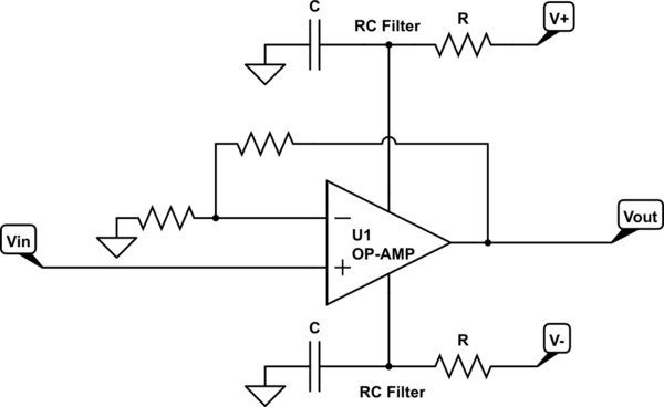
Another example with a good visual would be the use of a simple RC filter sometimes placed on the power pins of an op-amp, (see the schematic below). In this case the series resistance is intentional, the filter components reduce undesired noise from getting to the power pins. If the resistor value is increased the filtering also increases but at the same time the voltage would be reduced at the power pins (due to IR losses). So the amount of filtering is a compromise between these effects. In some cases the current drawn by the op-amp is small so the voltage drop is not significant. However, if the supply voltages are initially low or if the op-amp draws a higher current it may be possible to increase the capacitor value and decrease the resistor value, thereby reducing the IR loss.

schematic

simulate this circuit – Schematic created using CircuitLab

\$\endgroup\$
1
\$\begingroup\$

In your current loop you have five elements:

  • Two CPU blocks, which I will call "loads", Z1 and Z2.
  • Two resistances, the ones whose values we control in this experiment, whose values I will call R1 and R2
  • A voltage source of 5V, which I'll label V1.

In your description of the scenario, those loads seem to just "adopt" whatever voltage remains after the resistors have taken up whatever they take up. This is not correct. Their own resistance, even if that were to vary from moment to moment, will also feature in the calculations of this system's behaviour.

By changing R1 and R2, you do indeed modify the amount of current flowing in the loop, and therefore the voltage across R1 and R2 will be influenced somewhat, but the amount those voltages change depends also upon the resistance of the loads.

The entire loop must be modelled as four resistive elements, not two:
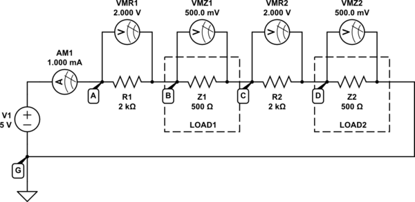
schematic

simulate this circuit – Schematic created using CircuitLab

There's an ambiguity in your question. When you say that CPU block1 (Z1) "sees a voltage of 2.5V", It's not clear what you mean. Similarly you state that Z2 "sees 0V", which suggests that you are referring to the absolute voltage (potential) that appears at nodes B and D above. Your numbers don't add up, as I'll try to demonstrate.

I have installed four voltmeters, but these devices only ever tell you the difference in voltage between two points in a circuit. Absolute voltages don't exist, only voltage across things, which we call "potential difference". When I say "across" I mean that each element may indeed have some potential at one end, and a different potential at the other, but all we as humans can know is the difference between those two values, never the absolute potential at either end.

This means that it doesn't ever matter what the absolute potential at any point is; only the difference in potentials matters, the difference that appears across things. If you somehow manage to raise the absolute voltage at node A by 1000V, all you've done is raise all absolute potentials everywhere in the circuit by that same amount, but the differences everywhere remain exactly the same, and the circuit's behaviour doesn't change at all.

It's possible to quote absolute potentials, but only if you first indicate where "zero volts" is, which I have done above using the "ground" symbol. I have labelled that as node G, a node which I declare to have potential (voltage) 0V. With that known by all readers of my schematic, when I state that A must be 5V higher in potential (due to V1) I can then state that absolute potential at node A \$V_A=+5V\$, everyone can agree. However everyone is also aware that absolute potentials don't really exist (where in the universe is zero volts, really?), and this convention/notation is merely a matter of convenience.

So we have to be careful when we quote voltages, and from here on all values that I quote will refer to a potential difference across an element. That is, the voltage across R1 is \$V_{R1}=2V\$, as displayed on meter VMR1. I don't care at all about the absolute potentials at A and B, only the difference between them.

The first correction to make is to your assertion that the current flowing will be 1.25mA. You assumed wrongly that the loads did not play a role in the calculation of this figure. In fact current depends on the resistances of all elements in the path, including the loads, which means that the correct calculation is:

$$ I = \frac{V_1}{R_{TOTAL}} = \frac{5V}{2000\Omega + 500\Omega + 2000\Omega + 500\Omega} = \frac{5V}{5000\Omega} = 1mA $$

That is assuming that the loads have 500Ω resistance. They won't have that, and in fact their resistance will change depending on what they're doing at the time, and many other factors impossible to summarize here. So that current will not be correct in any real circuit, but will still allow us to illustrate the system's behaviour in the context of your question.

This 1mA is shown on ammeter AM1.

Now let's reduce R1 and R2 to 1kΩ:
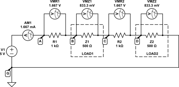
schematic

simulate this circuit

Now the total resistance around the loop has reduced:

$$ R_{TOTAL} = 1k\Omega + 500\Omega + 1k\Omega + 500\Omega = 3k\Omega $$

Therefore, the current flowing will indeed have increased, as you would expect:

$$ I = \frac{V_1}{R_{TOTAL}} = \frac{5V}{3k\Omega} = 1.667mA $$

However, Ohm's law must still apply, and each individual element will still have a potential difference across it in accordance with that law:

$$ \begin{aligned} V_{R1} &= I \times R_1 = 1.667mA \times 1k\Omega = 1.667V \\ \\ V_{Z1} &= I \times Z_1 = 1.667mA \times 500\Omega = 0.833V \\ \\ \end{aligned} $$ and so on.

If you wished to quote some absolute potentials at nodes G, A, B, C and D, the process goes as follows:

  • We have declared \$V_G = 0V\$ using the ground symbol, that's a given.
  • Node A must be 5V higher in potential than G, due to the voltage source V1, so \$V_A = V_G + V_1 = 0V + 5V = +5V\$.
  • Current inside a resistor always flows from high potential to low. In other words, the end of a resistor where current enters always has the higher potential. Current is flowing from left to right here, so the left ends of each resistor and load is higher in potential that the right end.
    Node B must be 1.667V lower than A (\$V_{R1} = 1.667V\$ shown on meter VMR1), so \$V_B = V_A - V_{R1} = (+5V) - 1.667V = +3.333V\$
  • \$V_C = V_B - 0.833V = +2.500V\$
  • \$V_D = V_C - 1.667V = +0.833V\$

Kirchhoff's Voltage Law (KVL) states that the sum of all potential differences across elements around a loop must be zero. That means if you travel a round any loop in a circuit, accumulating all the changes (increases and decreases) in potential as you jump from node to node, you should always end up at the same potential you started with:

$$ V_G = V_D - V_{Z2} = +0.833V - 0.833V = 0V $$

which is correct, since that's the potential we declared node G to have right from the start, so KVL is not violated.

I recommend you apply this same analysis to the first circuit, in which \$R_1 = R_2 = 2k\Omega\$, to cement everything I've just said. Demonstrate for yourself that Ohm's Law and KVL are not violated, and reinforce your understanding of absolute potentials and potential differences.

\$\endgroup\$
0
\$\begingroup\$

Experiments

To explain this phenomenon, it is necessary to specify from which source the circuit is powered - voltage or current. So let's look at both cases.

To simplify the schematics, in the CircuitLab experiments below, I have used "visualized resistors" - ammeter (as R1) and voltmeter (as R2) with 1 kΩ internal resistance. You can change it in the CircuitLab parameters window.

Also, in the DC Sweep Simulations below the resistance increases because in CircuitLab the swept quantity can only increase.

Voltage-supplied circuit

This is the most common arrangement (the OP's case).

Voltage divider

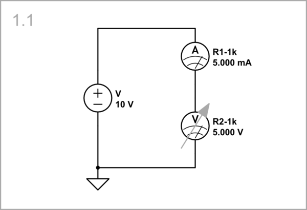
Imagine that in a circuit of two resistors R1 and R2 in series (aka voltage divider) supplied by a constant voltage source V, you change the resistance R2 (OP's arrangement).

schematic

simulate this circuit – Schematic created using CircuitLab

Indeed, when the resistance R1 decreases, the current I increases but to a lesser extent (ie, R2 partially affects the current). The reason for this is that the current is not determined solely by R2 but by R1 + R2 so I = V/(R1 + R2), while the voltage drop across R2 is determined only by R2 (VR2 = I.R2). So you have a product of two quantities (resistance and current) that change simultaneously and oppositely but to different degrees. As a result, the voltage drop across R2 changes non-linearly - VR2 = V.R2/(R1 + R2).

STEP 1.1a

STEP 1.1b

Resistor

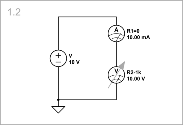
For completeness, let's consider the extreme case when R1 = 0, i.e. the resistor is powered directly (through an "ideal" ammeter with zero resistance) from the voltage source.

schematic

simulate this circuit

Although it does not make much sense, we can imagine that R2 first sets the current I = V/R2 (Ohm's law) and then conversely the voltage V = I.R2 (the dual Ohm's law). So R2 affects the current entirely.

STEP 1.2a

STEP 1.2b

Current-supplied circuit

Voltage divider

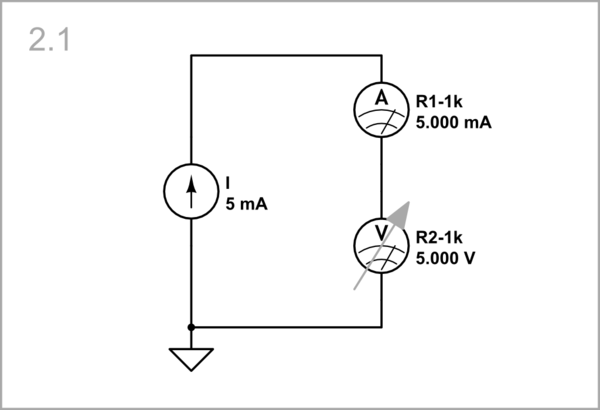
OP's difficulty with explaining the above circuit comes from the fact that both the resistance R2 and the current through it change. But let's see what happens if the circuit is supplied by a constant current source I, and you change the resistance R2 again.

schematic

simulate this circuit

Now, when the resistance R2 decreases, the current does not change because the circuit is current supplied. As a result, the voltage drop across R2 decreases as above but linearly (VR2 = I.R2).

STEP 2.1a

STEP 2.1b

Resistor

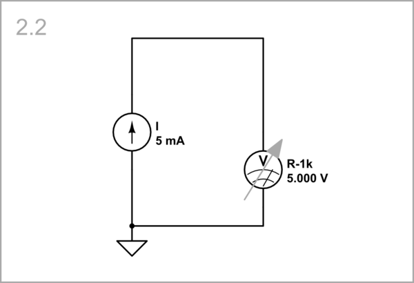
It is obviously that R1 does not play any role here and can be removed.

schematic

simulate this circuit

As you can see, the results are the same.

STEP 2.2a

STEP 2.2b

Conclusions

If in a circuit of several resistors in series, we change the resistance R of one of the resistors, the current I changes to a lesser extent than R. Therefore, the voltage drop I.R across R changes in the same direction as R.

If we scale the resistances of a voltage divider, only the current changes; its ratio R2/(R1 + R2) and output voltage do not change.

\$\endgroup\$
1
  • \$\begingroup\$ I invite the anonymous downvoter to provide some explanation for their downvote from yesterday; this would benefit everyone. \$\endgroup\$ Commented Nov 5, 2023 at 12:55

Your Answer

By clicking “Post Your Answer”, you agree to our terms of service and acknowledge you have read our privacy policy.

Not the answer you're looking for? Browse other questions tagged or ask your own question.