In your current loop you have five elements:
- Two CPU blocks, which I will call "loads", Z1 and Z2.
- Two resistances, the ones whose values we control in this experiment, whose values I will call R1 and R2
- A voltage source of 5V, which I'll label V1.
In your description of the scenario, those loads seem to just "adopt" whatever voltage remains after the resistors have taken up whatever they take up. This is not correct. Their own resistance, even if that were to vary from moment to moment, will also feature in the calculations of this system's behaviour.
By changing R1 and R2, you do indeed modify the amount of current flowing in the loop, and therefore the voltage across R1 and R2 will be influenced somewhat, but the amount those voltages change depends also upon the resistance of the loads.
The entire loop must be modelled as four resistive elements, not two:
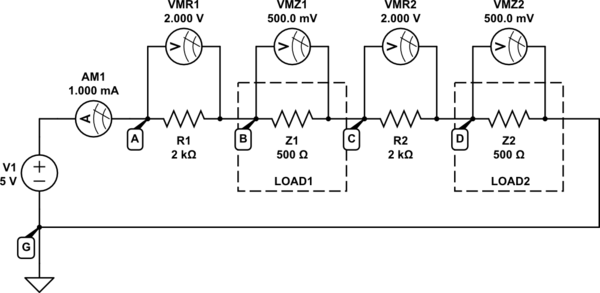
simulate this circuit – Schematic created using CircuitLab
There's an ambiguity in your question. When you say that CPU block1 (Z1) "sees a voltage of 2.5V", It's not clear what you mean. Similarly you state that Z2 "sees 0V", which suggests that you are referring to the absolute voltage (potential) that appears at nodes B and D above. Your numbers don't add up, as I'll try to demonstrate.
I have installed four voltmeters, but these devices only ever tell you the difference in voltage between two points in a circuit. Absolute voltages don't exist, only voltage across things, which we call "potential difference". When I say "across" I mean that each element may indeed have some potential at one end, and a different potential at the other, but all we as humans can know is the difference between those two values, never the absolute potential at either end.
This means that it doesn't ever matter what the absolute potential at any point is; only the difference in potentials matters, the difference that appears across things. If you somehow manage to raise the absolute voltage at node A by 1000V, all you've done is raise all absolute potentials everywhere in the circuit by that same amount, but the differences everywhere remain exactly the same, and the circuit's behaviour doesn't change at all.
It's possible to quote absolute potentials, but only if you first indicate where "zero volts" is, which I have done above using the "ground" symbol. I have labelled that as node G, a node which I declare to have potential (voltage) 0V. With that known by all readers of my schematic, when I state that A must be 5V higher in potential (due to V1) I can then state that absolute potential at node A \$V_A=+5V\$, everyone can agree. However everyone is also aware that absolute potentials don't really exist (where in the universe is zero volts, really?), and this convention/notation is merely a matter of convenience.
So we have to be careful when we quote voltages, and from here on all values that I quote will refer to a potential difference across an element. That is, the voltage across R1 is \$V_{R1}=2V\$, as displayed on meter VMR1. I don't care at all about the absolute potentials at A and B, only the difference between them.
The first correction to make is to your assertion that the current flowing will be 1.25mA. You assumed wrongly that the loads did not play a role in the calculation of this figure. In fact current depends on the resistances of all elements in the path, including the loads, which means that the correct calculation is:
$$ I = \frac{V_1}{R_{TOTAL}} = \frac{5V}{2000\Omega + 500\Omega + 2000\Omega + 500\Omega} = \frac{5V}{5000\Omega} = 1mA $$
That is assuming that the loads have 500Ω resistance. They won't have that, and in fact their resistance will change depending on what they're doing at the time, and many other factors impossible to summarize here. So that current will not be correct in any real circuit, but will still allow us to illustrate the system's behaviour in the context of your question.
This 1mA is shown on ammeter AM1.
Now let's reduce R1 and R2 to 1kΩ:
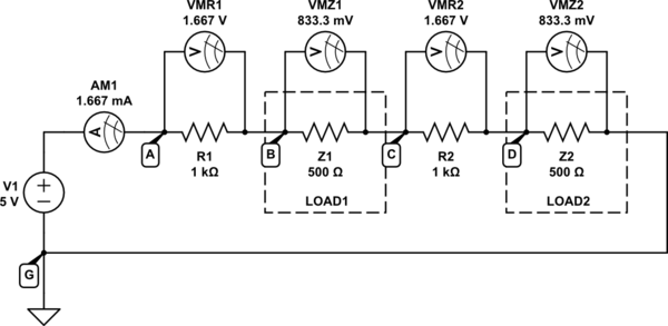
simulate this circuit
Now the total resistance around the loop has reduced:
$$ R_{TOTAL} = 1k\Omega + 500\Omega + 1k\Omega + 500\Omega = 3k\Omega $$
Therefore, the current flowing will indeed have increased, as you would expect:
$$ I = \frac{V_1}{R_{TOTAL}} = \frac{5V}{3k\Omega} = 1.667mA $$
However, Ohm's law must still apply, and each individual element will still have a potential difference across it in accordance with that law:
$$
\begin{aligned}
V_{R1} &= I \times R_1 = 1.667mA \times 1k\Omega = 1.667V \\ \\
V_{Z1} &= I \times Z_1 = 1.667mA \times 500\Omega = 0.833V \\ \\
\end{aligned}
$$
and so on.
If you wished to quote some absolute potentials at nodes G, A, B, C and D, the process goes as follows:
- We have declared \$V_G = 0V\$ using the ground symbol, that's a given.
- Node A must be 5V higher in potential than G, due to the voltage source V1, so \$V_A = V_G + V_1 = 0V + 5V = +5V\$.
- Current inside a resistor always flows from high potential to low. In other words, the end of a resistor where current enters always has the higher potential. Current is flowing from left to right here, so the left ends of each resistor and load is higher in potential that the right end.
Node B must be 1.667V lower than A (\$V_{R1} = 1.667V\$ shown on meter VMR1), so \$V_B = V_A - V_{R1} = (+5V) - 1.667V = +3.333V\$
- \$V_C = V_B - 0.833V = +2.500V\$
- \$V_D = V_C - 1.667V = +0.833V\$
Kirchhoff's Voltage Law (KVL) states that the sum of all potential differences across elements around a loop must be zero. That means if you travel a round any loop in a circuit, accumulating all the changes (increases and decreases) in potential as you jump from node to node, you should always end up at the same potential you started with:
$$ V_G = V_D - V_{Z2} = +0.833V - 0.833V = 0V $$
which is correct, since that's the potential we declared node G to have right from the start, so KVL is not violated.
I recommend you apply this same analysis to the first circuit, in which \$R_1 = R_2 = 2k\Omega\$, to cement everything I've just said. Demonstrate for yourself that Ohm's Law and KVL are not violated, and reinforce your understanding of absolute potentials and potential differences.


