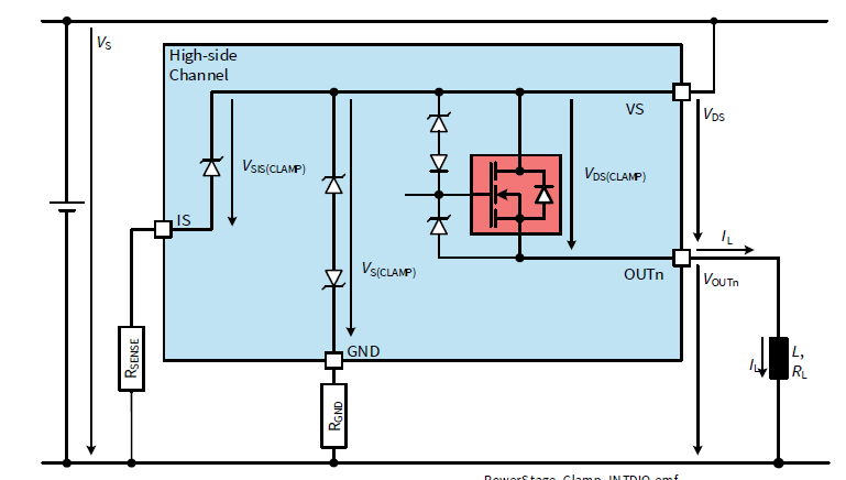
Hello I would like to design protection for HSD, BTS7200-2EPA against inductive load. Spec data for the inductive load is limited. But the PCB was designed for 2.5A peak, and approximate L and R_L values were obtained as 140mH and 9.5 ohm, respectively through measurement. (Approximately 1.4A at 12V)
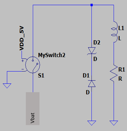
I got to know that putting a freewheel diode and Zener in series in parallel to load is generally used to protect against reverse voltage from inductive load when switched off.
First of all, can you explain how the concept works during the demagnetization? How fast is the current ramp and how is energy dissipated during the reverse voltage clamp etc.
And next step is how should I select D1 and D2? In consideration to V_Breakdown, Power rating etc.


