1
\$\begingroup\$

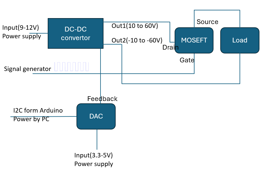
I have the following schematic as the verification and validation setup for our DC-DC converter:

enter image description here

The idea is that by using a DAC, we can manipulate the output voltage. We plan to send commands to the DAC through I2C, using an Arduino. Therefore, the GND of the PC or laptop should be connected through the GND of the power supply.

Next, we want to involve a load in the circuit by using a MOSFET. The gate of the MOSFET will be connected to a signal generator. We will use this signal to trigger the oscilloscope to observe the effect of the load on the output voltage.

My question is: considering there will be three different GNDs (the first one from the PC or laptop through the Arduino, the second one from the signal generator, and the third one from the power supply), at some point, I need to connect these three GNDs together. Is there any potential issue when doing so, considering there might be a slight potential difference between these three GNDs?

Regards

\$\endgroup\$
6
  • 3
    \$\begingroup\$ Generating two voltage rails which you put in series doesn't make sense and will make it very hard to drive the MOSFET with a function generator since the MOSFET will be floating relative to ground. \$\endgroup\$ Commented Jul 24 at 13:24
  • \$\begingroup\$ @user1850479 Would you please let me know what do you mean by this " two voltage rails which you put in series"? \$\endgroup\$
    – Andromeda
    Commented Jul 24 at 13:39
  • \$\begingroup\$ Your drawing shows two voltage rails (out1 and out2) wired in series. \$\endgroup\$ Commented Jul 24 at 13:53
  • 2
    \$\begingroup\$ Your gate drive needs to be source referenced, i.e. top of load. For future reference, please use standard N-MOSFET symbol instead of a block. \$\endgroup\$
    – winny
    Commented Jul 24 at 13:55
  • \$\begingroup\$ @Andromeda What is the dc dc converter? Is it isolated? \$\endgroup\$
    – Voltage Spike
    Commented Jul 24 at 15:27

1 Answer 1

1
\$\begingroup\$

Do very good grounds with good and short connection between the source voltage or data and source ground (e.g. when you bring power from power supply, the ground connector going back to it should be close power connector, in electrical sense. So currents flowing back to the power supply have to have the shortest path possible).

I'm not very sure about the whole concept, but that might be another story.

\$\endgroup\$
1
  • \$\begingroup\$ thanks for the useful answer, I appreciate it, would you please vote on my question as well. \$\endgroup\$
    – Andromeda
    Commented Jul 25 at 9:23

Your Answer

By clicking “Post Your Answer”, you agree to our terms of service and acknowledge you have read our privacy policy.

Not the answer you're looking for? Browse other questions tagged or ask your own question.