2
\$\begingroup\$

I am learning about opamp noise calculation in this document.You can see calculation example:1 in page no:7.

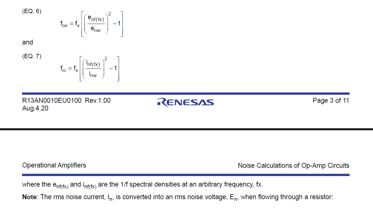
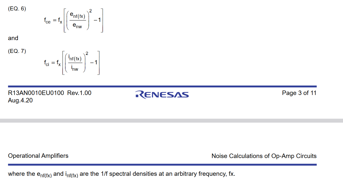
Below equations are used for calculating the corner frequencies.

enter image description here

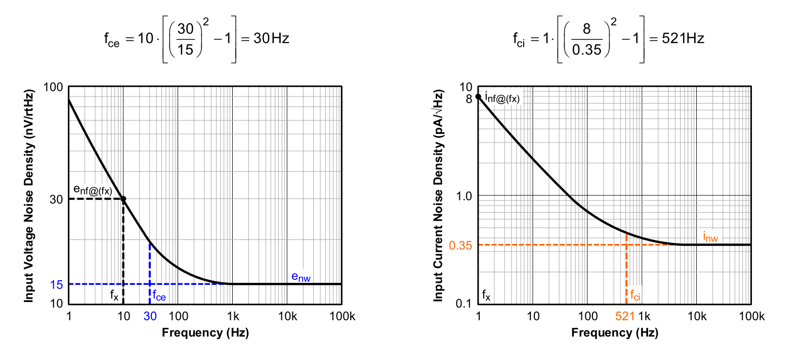
The calculation are given below.

enter image description here

My question is why they take 10Hz as fx for calculating fce and 1hz for calculating fci.

Is there any rule of thumb for selecting fx

\$\endgroup\$

2 Answers 2

0
\$\begingroup\$

My question is why they take 10Hz as fx for calculating fce and 1hz for calculating fci. Is there any rule of thumb for selecting fx?

Well... No not really and the datasheet specifically says it is a 1/f spectral density at an arbitrary frequency, which is fx. Generally speaking, however, putting 1/f (or pink/flicker) noise through a low pass filter typically yields roughly 0.7Hz for a cutoff/corner frequency. If you do a frequency sweep between 0Hz to 10Hz, you will see more granular noise between the two frequencies. After 10Hz, you are practically at an infinitesimally small amount noise amplitude as you enter white noise region.

So I suppose in a way, your fx frequency should not exceed 10Hz if you want to study significant noise amplitude for DC voltage supply operations on an amplifier.

\$\endgroup\$
3
  • \$\begingroup\$ Why didn't they take 10Hz for fci \$\endgroup\$
    – Confused
    Commented Oct 14 at 18:51
  • \$\begingroup\$ @Confused \$f_{c_i}\$ is the corner frequency for the noise current. You probably meant to say \$f_{x_i}\$, and the answer is nobody knows! It may have yielded a more convenient or more reliable measurement. \$\endgroup\$
    – a360pilot
    Commented Oct 14 at 20:48
  • \$\begingroup\$ @Confused Since it's arbitrary, it's likely to provide the reader information with different testing conditions. \$\endgroup\$
    – Colin
    Commented Oct 15 at 1:24
0
\$\begingroup\$

Datasheet

According to the first line on the next page, these frequencies are just arbitrary numbers in the flicker noise plots, and the \$e_{nf(f_x)}\$, \$i_{nf(f_x)}\$ terms must be adjusted accordingly. If you pay close attention, the substituted numbers agree with the figures. \$e_{nf(f_x)} = 30\$ is taken at \$ f_x = 10\,\text{Hz}\$ while \$i_{nf(f_x)} = 8\$ is taken at \$ f_x = 1\,\text{Hz}\$.

\$\endgroup\$

Your Answer

By clicking “Post Your Answer”, you agree to our terms of service and acknowledge you have read our privacy policy.

Not the answer you're looking for? Browse other questions tagged or ask your own question.