0
\$\begingroup\$

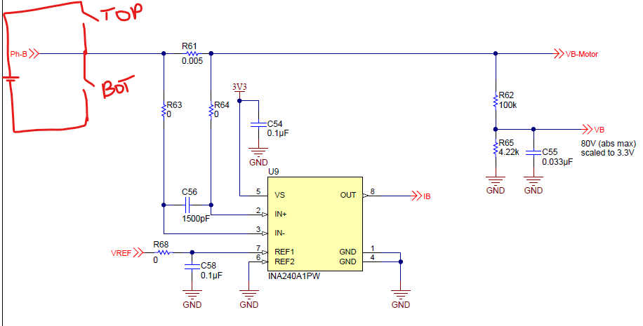
We have a working circuit that measures motor phase currents and passes it along to an MCU's internal ADC. This is the circuit: Current measurement_1 Notice that the output will be 'inverted' , so in software we invert it back to get back the correct value.
We want to replace the above circuit with a Sigma-Delta Modulator such as the AMC1303M0510. Sigma-Delta ADC simplified schematic Reading through the data sheet , they say that if the differential input is 50mv , that would mean a duty cycle pulses of 89.06 %., The MCU's SDFM module reads these pulses and gives out a value based on the resolution set in software.(As shown in the figure above) Digital output description
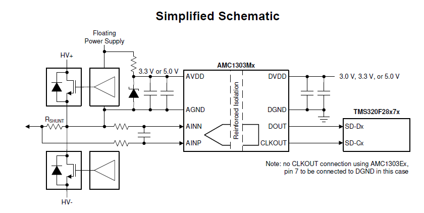
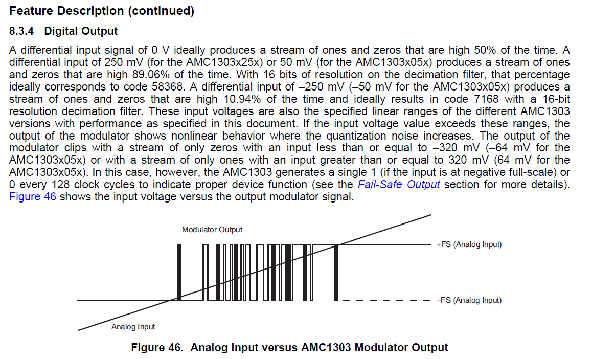
  • The 'Differential input' here is referred as (AINN - AINP) OR (AINP - AINN)?
  • If voltage at AINN > AINP, does this mean the Duty cycle is between (50 to 89.06)

OR

  • If voltage at AINP > AINN, does this mean the Duty cycle is between (50 to 89.06)

Please help clear this confusion. Thankyou!

\$\endgroup\$
2
  • \$\begingroup\$ Note that the AMC1303 is a delta-sigma modulator, not a complete ΔΣ ADC. \$\endgroup\$
    – Hearth
    Commented Oct 29 at 3:32
  • \$\begingroup\$ Hi Hearth, yes i am aware it is a modulator , i have corrected in my post. \$\endgroup\$
    – AK47
    Commented Oct 29 at 3:39

1 Answer 1

0
\$\begingroup\$

If you see this you can get some idea

well i also work on a 400V motor driver but I use AMC1300 IC .you want see some details in data sheet .

get know the connections

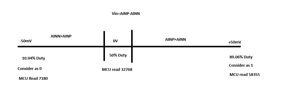
here the long story short . Vin=Ainp-Ainn

INP=0V (Exactly) OP=will give a pulse of 50% duty cycle respect to your frequency.

INP=+50mv(Full scale) OP=1 pulse with 89.06% duty cycle (MCU read as "1" )

INP=-50mv(Full Scale) OP=1 pulse with 10.94% duty cycle (MCU read as "0" )

Clipping mode :

Only Zeros(pulse width 10.96%) are transmitted if input is ≤ –64 mV.

Only Ones (Pulse width 89.06%)are transmitted if input is ≥ +64 mV.

so the consolidated answer is

consider 0V as a center point

If AINP>AINN: Duty cycle is 50% to 89.06% (positive input).

If AINN>AINP: Duty cycle is 50% to 10.94% (negative input).

your assumption is correct.

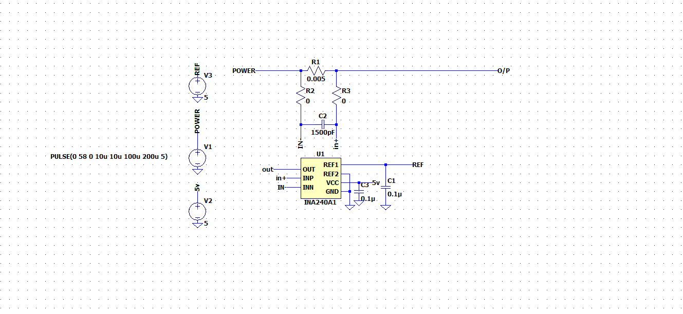
This is the simulation I've done: Actually it has to be done more precisely and the ADC output is read in MCU only. Schematic of Simulation

Output trace of Simulation

\$\endgroup\$
2
  • \$\begingroup\$ Thx for your answer Vikraman, By any chance, Have you confirmed this on an oscilloscope? \$\endgroup\$
    – AK47
    Commented Oct 30 at 2:35
  • \$\begingroup\$ Actually not . I done a simulation for this. I will share the Simulation results. \$\endgroup\$
    – Vikraman
    Commented Nov 7 at 9:37

Your Answer

By clicking “Post Your Answer”, you agree to our terms of service and acknowledge you have read our privacy policy.

Not the answer you're looking for? Browse other questions tagged or ask your own question.