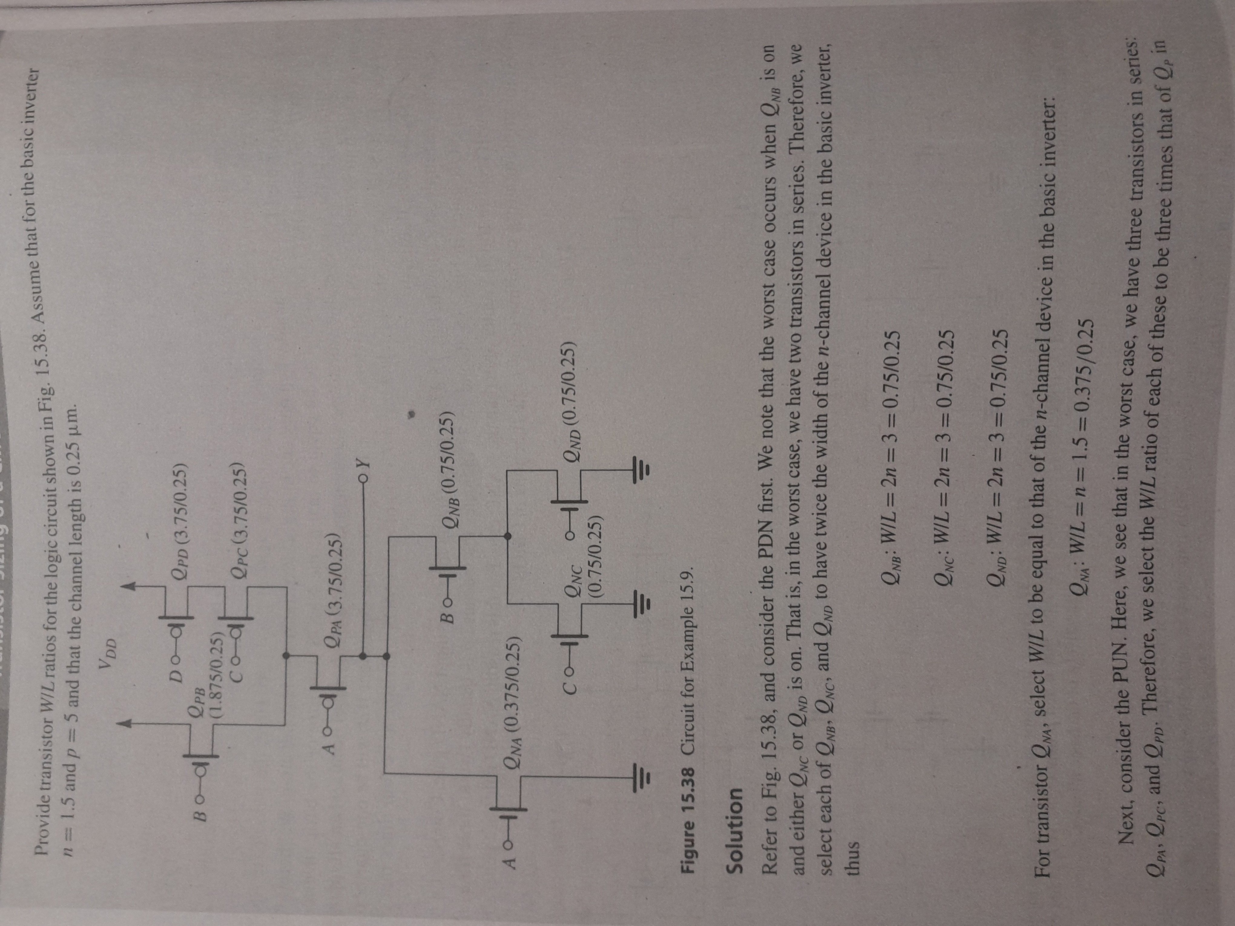
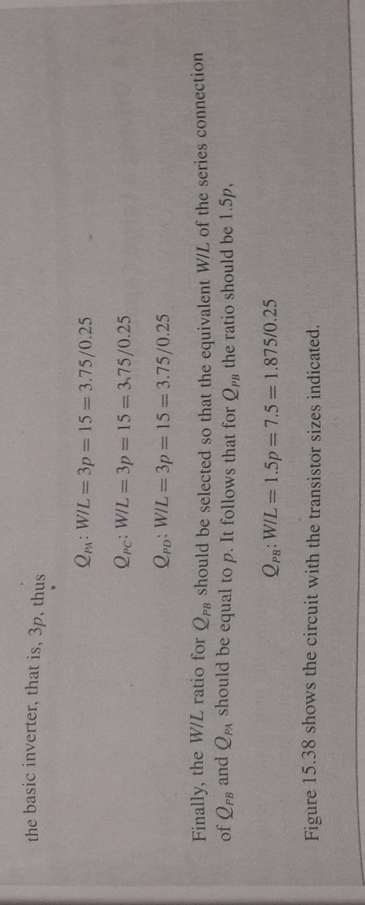
Here is a Digital circuit which shows a type of logic circuit in which there are two networks which are the pull up network (PUN) in the top and pull down network (PDN) at the bottom with the line containing Y at the middle. These networks pull up or pull down the voltage level which is supposed to be at \$V_{DD}\$. This is an example from a book "Microelectronic circuis",7e by Sedra and Smith, OUP.
In this, several MOSFETS are connected in series or parallel in the PUN or PDN. The PUN or PDN circuit is supposed to have an equivalent W/L value so that the PUN or PDN with various combinations of inputs (High or Low) would function as a MOSFET with a \$\frac{W}{L}\$ value. L is assumed to be constant at 0.25 µm.
The MOSFETs in the PUN and PMOS transistors while MOSFETs in PDN are NMOS transistors. Please note their symbols as shown. The circuit is so designed so that different combinations of inputs, the maximum equivalent \$\frac{W}{L}\$ value of a series combination of MOSFETs should not exceed certain value.
Equation for calculation of \$\frac{W}{L}\$ for series combination of MOSFETs is:
$$ \frac{1}{(\frac{W}{L})} = \frac{1}{(\frac{W}{L})_1} + \frac{1}{(\frac{W}{L})_2} + \frac{1}{(\frac{W}{L})_3} + \frac{1}{(\frac{W}{L})_4} +..... \frac{1}{(\frac{W}{L})_n}$$
Equation for calculation of \$\frac{W}{L}\$ for parallel combination of MOSFETs is: $$(\frac{W}{L}) = (\frac{W}{L})_1 +(\frac{W}{L})_2 + (\frac{W}{L})_3 + (\frac{W}{L})_4+.....(\frac{W}{L})_n$$
It is unknown for what application the circuit is used. Now, the question is about finding appropriate \$\frac{W}{L}\$ values for each of the MOSFETs in PUN and PDN for some logic function at the output. The calculation of \$\frac{W}{L}\$ values in the example seems strange as it doesn't explain for what purpose the \$\frac{W}{L}\$ values are calculated and why a particular \$\frac{W}{L}\$ value of some MOSFETs is chosen in the diagram.
Here is the example:
How are \$\frac{W}{L}\$ values of MOSFETs \$Q_{PB}\$ and \$Q_{NA}\$ calculated? What is the method to calculate them and others? Is there a step by step procedure to calculate them?
A detailed explanation is appreciated.
Reference: Microelectronic circuits- theory and applications, 7e, Sedra and smith, oup india, pages 1172,1173.


