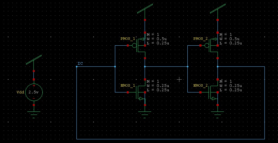
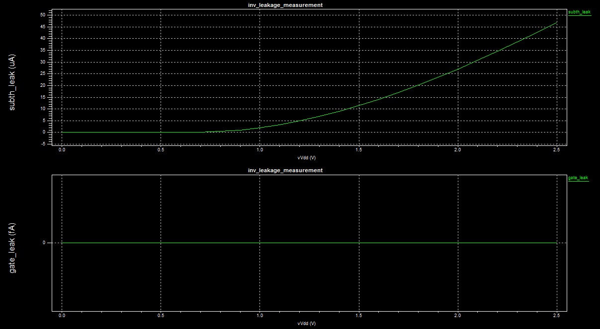
I would like to measure the leakage current of a CMOS inverter. As this current depends on the input, I decided to measure something average, namely, the leakage current of a ring with two CMOS inverters so that both PMOS and NMOS devices have an opportunity to be in both on and off states. I am using a SPICE simulator for this purpose. My circuit is as follows (not-that-relevant instructions are omitted):
X1 in  int dd ss bn bp inverter
X2 int in  dd ss bn bp inverter

Vdd dd 0 1
Vbp bp 0 1
Vbn bn 0 0
Vss ss 0 0

.ic V(in) = 0
.probe dc Ileak = par('abs(I(Vdd)) / 2')
where inverter is a subcircuit based on BSIM4 (v4.7) devices.
Since I have little experience in this area, I cannot really tell if what I am doing makes sense. I would be grateful if somebody could confirm that the circuit serves the desired purpose.
There is one more aspect that I would like to clarify. My global target is to get a rough estimate of the leakage current of a larger circuit based on the measurements of this little ring. I understand that this estimate will probably be (very very very) vague and abstract. Nevertheless, such an approach is good enough for me. However, I would like to push this estimate as far as I can, and I am wondering if it would be better to include some loads in the circuit between the two inverters as shown below:
.subckt load in dd ss bn bp
X1 in  int dd ss bn bp inverter M = 3
X2 int out dd ss bn bp inverter M = 12
.ends

X1   in int dd ss bn bp inverter
X1_1 int dd ss bn bp load

X2   int in dd ss bn bp inverter
X2_1 in dd ss bn bp load

Vdd dd 0 1
Vbp bp 0 1
Vbn bn 0 0
Vss ss 0 0

.ic V(in) = 0
.probe dc Ileak = par('abs(I(Vdd)) / 2')
where load is a subcircuit with a couple of slightly enlarged inverters.


.iccommand; I have updated the code above. \$\endgroup\$