I have an assignment in college and I would like to ask some questions:
You are to design a Mealy state diagram for a safety device. Assume that two debounced push-buttons, A and B, are available to enter the combination. An electromechanical interlock guarantees that the buttons cannot be activated simultaneously. The lock should have the following features:
The combination is A-A-B-A-B-A. If this sequence is correctly entered, an output signal is asserted that causes the lock to open.
For any state, three B pulses in a row should guarantee to reset the control to its initial state.
When any out-of-sequence use of the A push-button occurs, an output is asserted that rings a bell to warn that the lock is being tampered with.
Once the lock is open, pressing either A or B will cause the lock to close without signaling an error. Draw a Mealy state diagram for this finite state machine. Indicate what each state represents and what input conditions cause state and output changes. Not everything may have been specified, so write down any assumptions you make.
I have to implement this Mealy machine using D flip-flops and MUX'es.
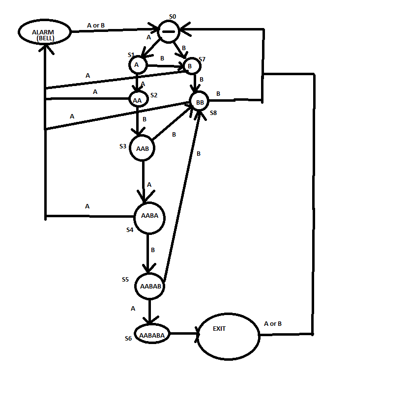
I have 10 states for my machine:
S0 -> "Input Start" // Nothing happened
S1 -> A
S2 -> AA
S3 -> AAB
S4 -> AABA
S5 -> AABAB
S6 -> AABABA -> this means EXIT
S7 -> B
S8 -> BB
S9 -> A -> "ALARM ON"
*****EDIT to add machine pic

My questions are:
- From what should I start in creating the truth table (on this specific assignment -- How can I think the necesarry flip-flops and MUX'es)?
- How can I create this specific diagram? Using only MUX'es and D-Flipflops?
