0
\$\begingroup\$

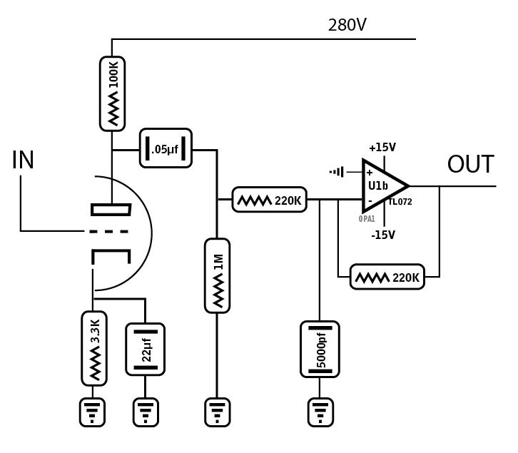
Wondering if anyone can advise on this tube triode (12ax7) preamp stage followed by an Op Amp buffer stage to correct the inverted signal. I wired it up and did not work. Before tho, I wired it with 22K resistors instead of 220K. Perhaps signal was overloading OpAmp? Also, should the impedance output from the OpAmp be essentially the same as if it were from the triode, just inverted?

enter image description here

\$\endgroup\$
1
  • \$\begingroup\$ This looks like an XY problem. What are you trying to accomplish here? Why does phase matter? Why use an opamp? \$\endgroup\$
    – John Doty
    Commented Aug 1, 2022 at 21:06

2 Answers 2

1
\$\begingroup\$

Middle 1 Meg Ohm resistor is not needed. Remove the 5000 pF capacitor from U1b (-) node.

You will have less gain than expected because the 220K input impedance of the op-amp stage is loading the output of the tube. But that's not enough to stop it from working.

What voltage are you running the tube's filament at?

\$\endgroup\$
5
  • \$\begingroup\$ 6.3v from a 3.15-0-3.15 CT TX The 5000pf is to filter out high freq noise from the signal \$\endgroup\$ Commented Feb 7, 2015 at 5:01
  • 1
    \$\begingroup\$ Regarding the 5000 pF capacitor: that is the wrong place to put that capacitor. There is a very good chance that it will cause the op-amp to oscillate. If you want to reduce the high-frequency response of the amplifier, put a capacitor across the feedback resistor on the op-amp. \$\endgroup\$ Commented Feb 7, 2015 at 5:53
  • \$\begingroup\$ Question: I assume that you have the two filaments inside the triode wired in parallel. My memory is hazy, but I think that you connect pins 4&5 together to one side of the filament supply and connect pin 9 to the other side of the filament supply. \$\endgroup\$ Commented Feb 7, 2015 at 5:54
  • \$\begingroup\$ Yes, the filaments are wired in parallel with pins 4 & 5 connected. A separate preamp in the circuit uses a 12ax7 also and works as it should. I'll move that cap over in parallel with the feedback resistor and reconnect with changes, see what happens and post results. Thank you @dwayne \$\endgroup\$ Commented Feb 7, 2015 at 6:16
  • \$\begingroup\$ The above filament connections are correct for a parallel connection with 6.3v in. But be sure you can supply the needed 300ma to fully heat the filaments. Here is the full wiki for the 12AX7 - en.wikipedia.org/wiki/12AX7 \$\endgroup\$
    – Nedd
    Commented Feb 7, 2015 at 6:19
0
\$\begingroup\$

There are a few things wrong here:

  1. As noted by Dwayne Reid, the cap on the op amp's negative input needs to be removed. A cap here will prevent the op amp from operating correctly.

  2. The circuit as shown will mostly serve to burn out the op amp. Consider the signal level at the tube's plate: it'll be around 200Vpp max. The op amp, with its +/-15V supply rails, cannot hope to invert that without clipping to those rails. When it does clip, you'll end up with at least 42Vpp at the op amp inverting input (very roughly, and very conservatively). This will damage or destroy any op amp not specifically designed to tolerate such high input voltages.

If you're truly trying to simply re-invert the tube's plate signal unchanged, however large that signal may be, you won't be able to do it with any common op amp: there's just no way to get a 200Vpp signal out of an op amp which is powered from +/-15V rails. There are high-voltage op amps available which you could use, but they are rare and expensive.

If it fits your requirements, another option is to reduce the plate signal level in one way or another such that a normal op amp can work with it. This will of course manifest as a reduction in the end-to-end gain of the circuit, but the resulting "mapping" of 200Vpp to 30Vpp may actually be the result you're looking for.
\$\endgroup\$

Your Answer

By clicking “Post Your Answer”, you agree to our terms of service and acknowledge you have read our privacy policy.

Not the answer you're looking for? Browse other questions tagged or ask your own question.