1
\$\begingroup\$

I want to measure the current grid voltage to synchronize a dc power supply with the grid using an inverter. Now I'm particularly interested in finding noise and harmonic information about the grid voltage.

So my plan is to use a transformer to to step the grid voltage down on two of the phases and use resistor dividers to get the voltage in an appropriate range for the ADCs of my dsp. Is this the best way to measure grid voltage for synchronization purposes(I'm particularly interested in unbalanced conditions).

Further more will i lose harmonic and noise information by using this method(through the inductance of the transformer)?

It's a bit of a repeat of this question though am interested if there are any other factors I need to take into account for voltage measurements for the purpose of grid synchronization. (If not i guess this question is kind of redundant)

\$\endgroup\$
2
  • \$\begingroup\$ Harmonic content up to what order? What sampling rate does your ADC support? E.g. 11th harmonic is only 550Hz. You should be able to measure it without any problem. Instead of using a transformer you can use a hall sensor. If thats too expensive consider an isolation amplifier - theres some from Avago, IIRC. \$\endgroup\$
    – kabZX
    Commented Jul 22, 2015 at 9:42
  • \$\begingroup\$ @kabZX I'm intrested in measuring the voltage and hall effect sensors measure current. So is it common practise to just make a resistive load and measure the current going into it with the hall sensor and working out the voltage by calculating I x R? \$\endgroup\$ Commented Jul 22, 2015 at 10:00

1 Answer 1

1
\$\begingroup\$

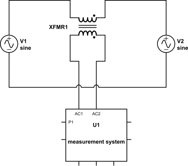
Grid sync requires that the voltage your inverter produces matches the grid voltage so the best way of achieving this is to compare, via a transformer, the two voltages. If perfectly matched, the transformer output will be zero and measurement errors are minimized.

schematic

simulate this circuit – Schematic created using CircuitLab

If there are harmonics present on one power signal relative to the other, the output voltage of the transformer will show these but at a reduced amplitude due to the increased eddy current losses as frequency rises. However, if the harmonics are identical on both, the harmonics will become zero when matched.

\$\endgroup\$
4
  • \$\begingroup\$ For this question I'm only interested in the measurement hardware/process used to obtain the grid voltage measurements(which will be used for sync, not the sync process itself). So from your answer you're saying to use a transformer to take the grid measurement and put these into the ADC(I'm guessing that's what you mean by compare them), is that right? Are there any further considerations I need to take into account to retain harmonic information when selecting a transformer or any instrument transformer with the right voltage range would suffice? \$\endgroup\$ Commented Mar 22, 2015 at 10:17
  • \$\begingroup\$ I'm saying your methodology is flawed compared to what I propose - the method I propose directly gives you an error voltage. When zero is outputted, the error is zero and no question about that. \$\endgroup\$
    – Andy aka
    Commented Mar 22, 2015 at 10:21
  • \$\begingroup\$ I'm not sure I like how the two sources are hardwired together through the transformer. Potential to transfer hazardous voltage from the inverter back onto a dead grid. \$\endgroup\$ Commented Mar 22, 2015 at 11:02
  • \$\begingroup\$ @Li-aungYip Saying they are hard wired together is wrong. The transformer primary seperates them. It will have a high impedance providing that the secondary doesn't have a ridiculously low load for measurement purposes. This is a measurement method not one for transferring power. \$\endgroup\$
    – Andy aka
    Commented Mar 22, 2015 at 12:42

Your Answer

By clicking “Post Your Answer”, you agree to our terms of service and acknowledge you have read our privacy policy.

Not the answer you're looking for? Browse other questions tagged or ask your own question.