7
\$\begingroup\$

I need to transform a bipolar sine wave (varies from -5 V to 5 V, 1 kHz) to a square wave for further digital processing (0 to 3.3 V), as in this image:
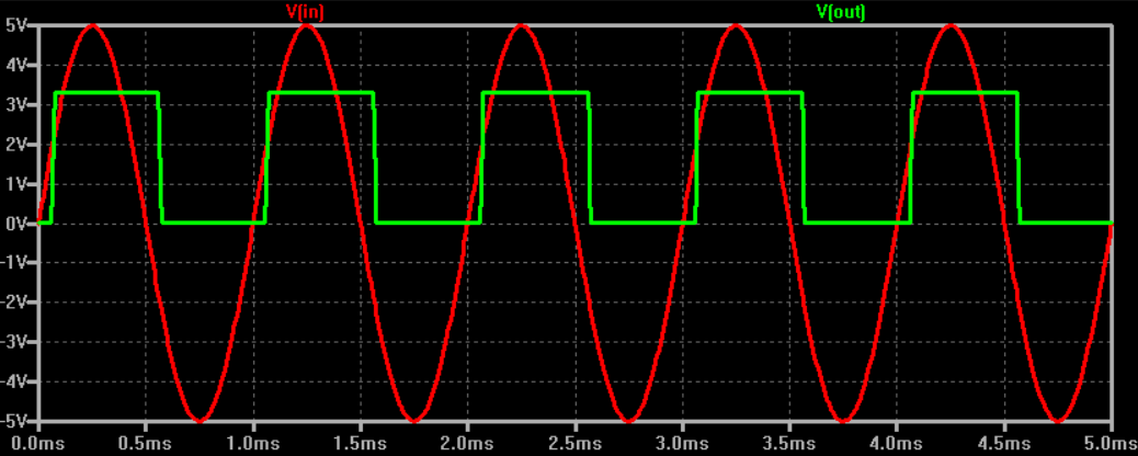
Sine wave to 3.3 V square wave

The important thing is that this sine wave can't be distorted, so there can't be any limiting diodes at the input.

I have got only 3.3 V and 5 V voltage supplies. An obvious way to go is an op-amp working as a Schmitt trigger, but I'm not sure it can handle -5 V at the input with a single positive 3.3 V supply.

Should I reduce the amplitude on the input by using a resistor divider? And perhaps add some offset voltage for the signal to fit the input voltage range of the op-amp?

\$\endgroup\$

5 Answers 5

11
\$\begingroup\$

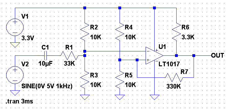
I would like to suggest that the comparator circuit shown by @hwengmgr could use some small improvements over what was posted.

Improvements include:

  1. Bigger capacitor value to reduce filter effect of the capacitor at frequency.
  2. Larger value resistors in dividers to reduce current load on source supply.
  3. Added hysteresis at the comparator to make the circuit less sensitive to noise that may be on the input waveform.
  4. Changed pullup resistor on output of comparator to a more sane value for 1mA load instead of 33mA.

enter image description here

enter image description here

This was simulated with LT-Spice. I used a model for a comparator that was built into the package library. You can substitute a comparator of choice as long as it is specified for operation at a Vdd of 3.3V.

The addition of the hysteresis feature necessitated the swapping of the '+' and '-' inputs of the comparator which causes an inversion of the output waveform. If this is a problem it can be easily flipped with a logic element. If you select a dual comparator the other half of the package could be used to invert the signal.

\$\endgroup\$
2
  • \$\begingroup\$ That's amazing. Thank you. That answers all of my answers :) Well... almost. What kind of capicator should I use as this coupling 10uF one? Some kind of film capicator? \$\endgroup\$
    – przeski
    Commented Apr 5, 2015 at 14:20
  • \$\begingroup\$ All good changes. To be fair I did not calculate much in my initial circuit but wanted to get the topology out there for comment. \$\endgroup\$
    – hwengmgr
    Commented Apr 5, 2015 at 18:12
6
\$\begingroup\$

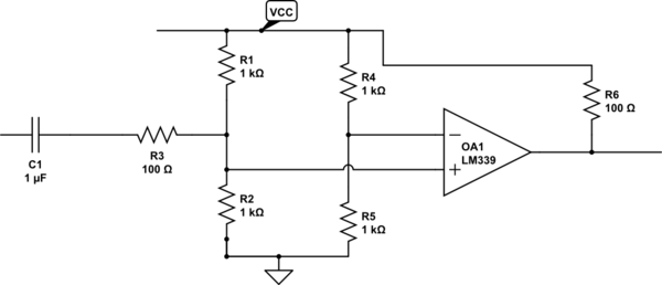
If its a continuous waveform, you can use a DC blocking capacitor and then use some resistors to set the DC common mode point and scale it as well. Then feed it into an LM339 comparator to get your digital output. Something like this. I have NOT calculated the resistor ratio's! But setting R3 will let you attenuate the incoming waveform. R4/R5 sets the threshold for switching the comparator output. R6 is needed because the LM339 is open collector output.

schematic

simulate this circuit – Schematic created using CircuitLab

\$\endgroup\$
3
  • 2
    \$\begingroup\$ I simulated this using PSpice and using 1uF and 1K for R3, I get a sine wave of 0 to 3V into the comparator, from an input of a sine wave going from -5V to +5V. \$\endgroup\$
    – hwengmgr
    Commented Apr 5, 2015 at 12:15
  • \$\begingroup\$ This is looking quite simple and I like it. Is there any reason I shouldn't be using higher values of resistors? For example 10k instead of 1k? \$\endgroup\$
    – przeski
    Commented Apr 5, 2015 at 13:06
  • \$\begingroup\$ you can use larger resistors. just remember that the capacitor will look like a resistor of value 1 / 2 * pi * 1khz * C (assuming 1KHz waveform) so you need to add it into the calculation for the attenuation. \$\endgroup\$
    – hwengmgr
    Commented Apr 5, 2015 at 13:26
6
\$\begingroup\$

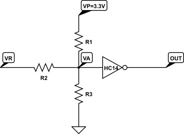
Take this schematic :

schematic

simulate this circuit – Schematic created using CircuitLab

Playing with Ohm's law, you get : \$R_{3} \times R_{1}\times V_{R}+R_{3} \times R_{2} \times V_{P} = (R_{1} \times R_{2}+R_{1} \times R_{3}+R_{2} \times R_{3}) \times V_{A}\$

If you set VR=0, VA shall be equal to VP/2=1.65V. You get :

\$R_{1} = \dfrac{R_{2} \times R_{3}}{R_{3}+R_{2}} \$ (or R1 = R2 parallel with R3)

For the maximum input voltage, 5V, VA=VP :

\$R_{3} = \dfrac{R_{2} \times V_{P}}{V_{Rmax} - V_{P}} = \dfrac{R_{2} \times 3.3}{5-3.3}\$


So.

With standard resistor values, you can pick : R1=10k, R2=16k, R3=30k

The gate should have a Schmidt trigger, and support any intermediate voltage at its input, for example an HC14. If you are afraid of exceeding the +5V/-5V range, you can add clamping diodes at the input of the inverter.

\$\endgroup\$
3
  • 1
    \$\begingroup\$ +1 for the good old superposition theorem in practice, with my favouritte R-based DC coupler. \$\endgroup\$
    – user20088
    Commented Apr 5, 2015 at 15:36
  • \$\begingroup\$ Note that you wrote that the sine wave should not be distorted, AC coupling could be better, as here the current drawn is different on the positive and negative halp periods. \$\endgroup\$
    – Grabul
    Commented Apr 5, 2015 at 16:52
  • \$\begingroup\$ your suggestion, as simple it is, solved my problem that I was working on for a looooong time. Sometimes it's better to KISS then to look for exotic solutions. Thank you. \$\endgroup\$
    – TommyS
    Commented May 30, 2021 at 1:07
2
\$\begingroup\$

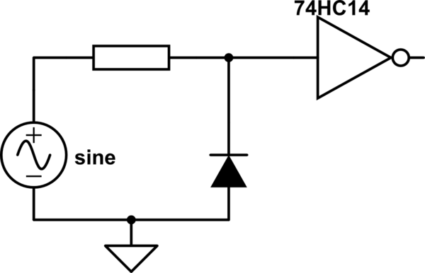
I would diode-clamp and use a 74HC14 digital chip for this job.

The 74HC14 is a digital inverter with schmitt input. This would then need to interface to 3v3 logic

schematic

simulate this circuit – Schematic created using CircuitLab

\$\endgroup\$
4
  • \$\begingroup\$ I think you'll also need a resistor in parallel with the diode to set the positive half cycle attenuation level. \$\endgroup\$
    – Andy aka
    Commented Apr 5, 2015 at 12:21
  • 1
    \$\begingroup\$ Thanks for answer. I'm afraid this circuit will cause some distortions during negative half cycle of sine wave, and additional op-amp buffer is probably needed. \$\endgroup\$
    – przeski
    Commented Apr 5, 2015 at 12:33
  • \$\begingroup\$ @andyaka yes, a parallel resistor will be needed \$\endgroup\$
    – user16222
    Commented Apr 5, 2015 at 13:57
  • \$\begingroup\$ @przeski did you try to simulate in circuitlab? That part isn't a 74hc14 as there isn't a part on their library. You need that to be a 14 as that has Schmitt input \$\endgroup\$
    – user16222
    Commented Apr 5, 2015 at 13:59
0
\$\begingroup\$

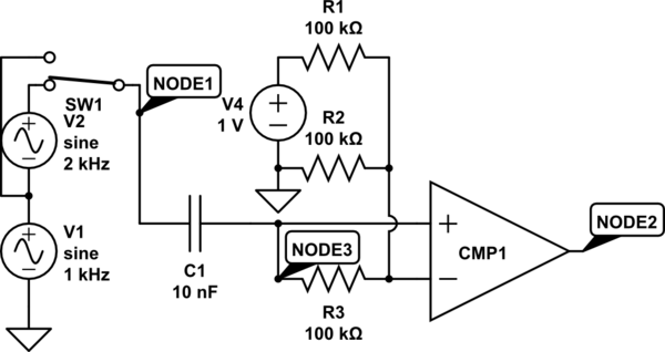
One thing you don't mention is whether the square wave needs to be square even if the sine wave may be distorted. I don't think a Schmidt trigger is needed here since the sine wave's dV/dt will be at its maximum near the switching point. A simple way to achieve a reasonable result would be:

schematic

simulate this circuit – Schematic created using CircuitLab

Once the circuit "warms up", it should give a 50%-duty-cycle square wave when given a sine-wave input. If given a distorted wave, however (in "build" mode, click "SW1" and click "properties" to switch its state) the output may not be quite square. There are other ways of setting up the circuit to ensure a 50%-duty-cycle output even in the presence of even harmonic distortion on the input, but this approach is nice and simple. The voltage divider for the comparator's reference voltage may be set to any convenient value; the duty cycle of the input is controlled by the symmetry of the input, rather than resistance ratios; designs to yield a symmetrical output when given a distorted input would have a duty cycle set by a resistance ratio.

\$\endgroup\$
2
  • \$\begingroup\$ C1 10pF is a ridiculously small capacitor whose impedance is nearly 16 megohms at the 1kHz operating frequency. The unspecified comparator will be unable to deliver much more than noise (or not even noise if its input leakage current through R3 is enough to keep the output low). \$\endgroup\$ Commented Apr 5, 2015 at 23:53
  • \$\begingroup\$ @cuddlyable3: It's 10nf; sorry NODE3 was placed to obscure that. The intention of the circuit was to suggest that the same voltage divider can be used for the DC bias as for the reference. Using separate dividers will cause any difference between them to contribute additional unwanted offset. \$\endgroup\$
    – supercat
    Commented Apr 6, 2015 at 3:30

Your Answer

By clicking “Post Your Answer”, you agree to our terms of service and acknowledge you have read our privacy policy.

Not the answer you're looking for? Browse other questions tagged or ask your own question.