2
\$\begingroup\$

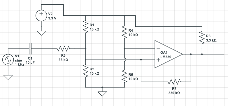
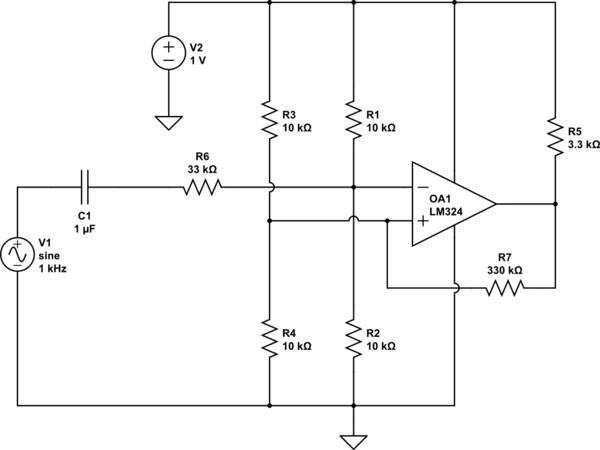
I'm trying to simulate the circuit posted here, which looks like this:

enter image description here

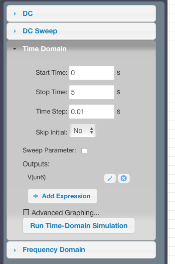
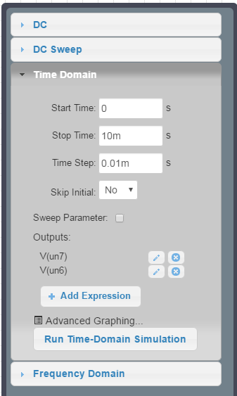
I'm running a transient analysis and have the following settings:

enter image description here

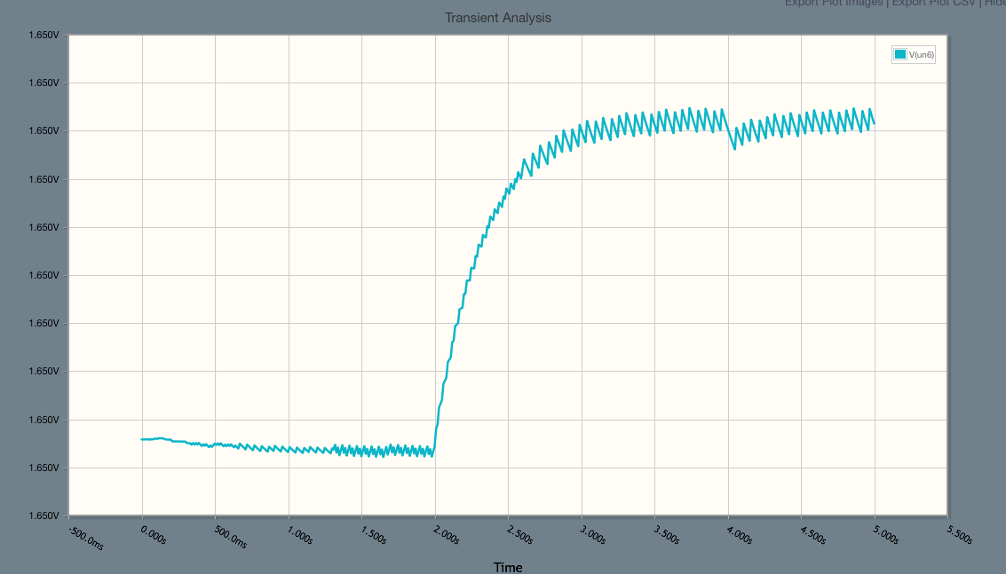
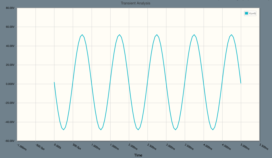
I expected to get the output as a square wave, but I'm getting this instead:

enter image description here

Does anyone know why I might be getting a zigzag wave rather than a square wave?

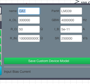
Here is the definition of LM339 used:

enter image description here

EDIT:

If I use a time step of 0.055ms and the stop time to just 5ms, I get the following:

enter image description here

which is still not a square wave.

The amplitude of the input signal is 5V.

\$\endgroup\$
10
  • 1
    \$\begingroup\$ If I'm reading things correctly, your signal is 1 KHz - one cycle per millisecond, but you are only sampling every 10 mS. The vertical lines on the graph are 500 mS apart, so you should get 500 cycles per square - pretty hard to see anything useful. \$\endgroup\$ Commented Dec 31, 2016 at 5:10
  • \$\begingroup\$ @PeterBennett Granted, I've now set the stop time to 1 and a 1ms step. The output is still not a square wave though. Please see edit. \$\endgroup\$
    – Kar
    Commented Dec 31, 2016 at 5:17
  • \$\begingroup\$ You need to sample a few times per cycle - perhaps 0.1 mS would work. Then set the graph to show just a few cycles per square - perhaps 5 mS per square would show something useful. \$\endgroup\$ Commented Dec 31, 2016 at 5:21
  • \$\begingroup\$ @PeterBennett I've now tried 0.1ms steps over 10ms. Please see update. \$\endgroup\$
    – Kar
    Commented Dec 31, 2016 at 5:23
  • 1
    \$\begingroup\$ Try using an "op amp with voltage rails". I tried an op amp as a comparator in CircuitLab without rails, and it goes to +/- 60V as in your second diagram. \$\endgroup\$ Commented Dec 31, 2016 at 6:05

2 Answers 2

1
\$\begingroup\$

You must be doing something wrong.

Here's the circuit I tried:

schematic

simulate this circuit – Schematic created using CircuitLab

Since the input signal is a 1kHz sine, you need to put much smaller numbers than the signal frequency as time-step. And also, since this is a comparator, amplitude of the input sine wave is quite important.

Here are the simulation parameters:

enter image description here

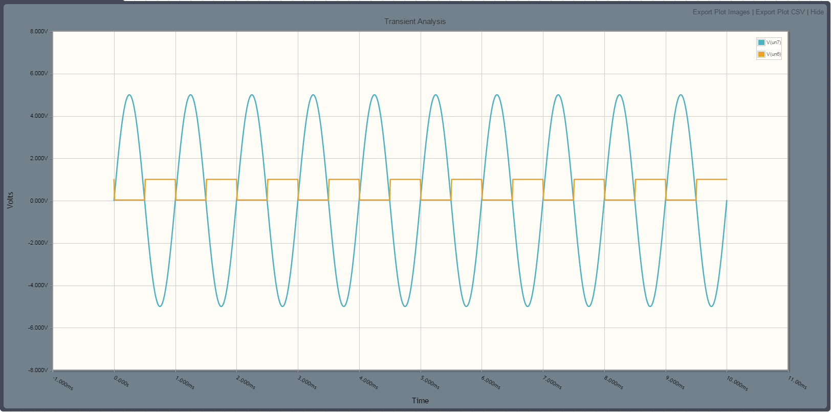
And here's the plot:

enter image description here

\$\endgroup\$
1
  • \$\begingroup\$ Thanks. @KenShirriff is right that op amp with voltage rails should be used instead. \$\endgroup\$
    – Kar
    Commented Dec 31, 2016 at 6:18
2
\$\begingroup\$

The problem is that a comparator's output swings between the positive voltage rail and negative voltage rail (more or less). If you use an op amp without voltage rails in CircuitLab, it doesn't know what these values should be, so it defaults to something like +/- 50V. This, of course, messes up your circuit, causing the crazy voltage swings you see in your second image. (The large default makes sense for a typical op amp circuit, which won't get near saturation. But for a comparator circuit, it's bad.)

The solution is to use "op amp with voltage rails", and connect it to a +1V source and ground. Then the comparator outputs 0 or 1V and everything works as expected.

\$\endgroup\$

Your Answer

By clicking “Post Your Answer”, you agree to our terms of service and acknowledge you have read our privacy policy.

Not the answer you're looking for? Browse other questions tagged or ask your own question.