0
\$\begingroup\$

I understand how a basic comparator op amp works and how a capacitor charges individually, but I can't seem to put it all together to make this circuit. I think I might be messing up with the voltage rails and grounds somehow. The point of the circuit is for the LEDs to light up at ~2 second intervals. The output of the comparator is supposed to transition from -13V to 12V where Vcc is +-15V. The op amps are TL081CP if that information helps. If anyone could give me some tips of what I might be missing or possibly add to this diagram with a little more detail that would really help a lot.
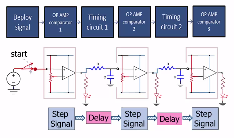
diagram of the timing circuit I need to build

\$\endgroup\$
4
  • \$\begingroup\$ well first of all, a bypass capacitor for each opamp would be good. The voltage at the first C rises slowly because of R between the first op-amp's output and the capacitor, forming a passive timing circuit with a time constant of T = RC. The potentiometer on the second op-amp is used to set a variable "compare trip point" for the opamp's output to change. This process is the same for the 3rd opamp in the chain. \$\endgroup\$
    – KyranF
    Commented Apr 10, 2015 at 3:47
  • \$\begingroup\$ Does the first LED come on? If not, check the voltage at both input terminals of the first op-amp. Also, it would be much better if you put in unique identifiers for each component. It makes it easier to talk about the circuit. \$\endgroup\$
    – user57037
    Commented Apr 10, 2015 at 5:04
  • \$\begingroup\$ A rather crude circuit.. but it should work. What's the problem? \$\endgroup\$ Commented Apr 10, 2015 at 13:02
  • \$\begingroup\$ I didn't draw this circuit, I'm just tasked to put it on a breadboard. The problem is it's still leaving out a bit too much information for me to figure out with my limited circuits knowledge. I've been trying to model it in my iCircuit software first and I just cannot get it to work. I deleted all of my unsuccessful attempts, but I guess I should try it again and repost so it's easier to diagnose. \$\endgroup\$
    – Austin
    Commented Apr 10, 2015 at 14:36

2 Answers 2

1
\$\begingroup\$

The output of the comparator is supposed to transition from -13V to 12V where Vcc is +-15V.

You may easily have damaged your LEDs. When the comparator is supposedly not driving a LED you will have generated -13V to ground across it (and its series resistor).

Most LEDs have a maximum reverse voltage of about 5V. It doesn't matter that there is a series resistor - it's the volts across the LED in reverse that damage them.

Try replacing the LEDs and putting a diode across each one to protect it from reverse voltages. If you have a data sheet try reading the absolute maximum ratings.

\$\endgroup\$
1
  • \$\begingroup\$ Nah, The spec sheets on LED's say 5V reverse, but I have yet to find one that can't take ~25V. And typically it's much more. (>50 to 100V) Try reverse biasing a few and see (100k ohm current limit R is good.) \$\endgroup\$ Commented Apr 10, 2015 at 13:01
0
\$\begingroup\$

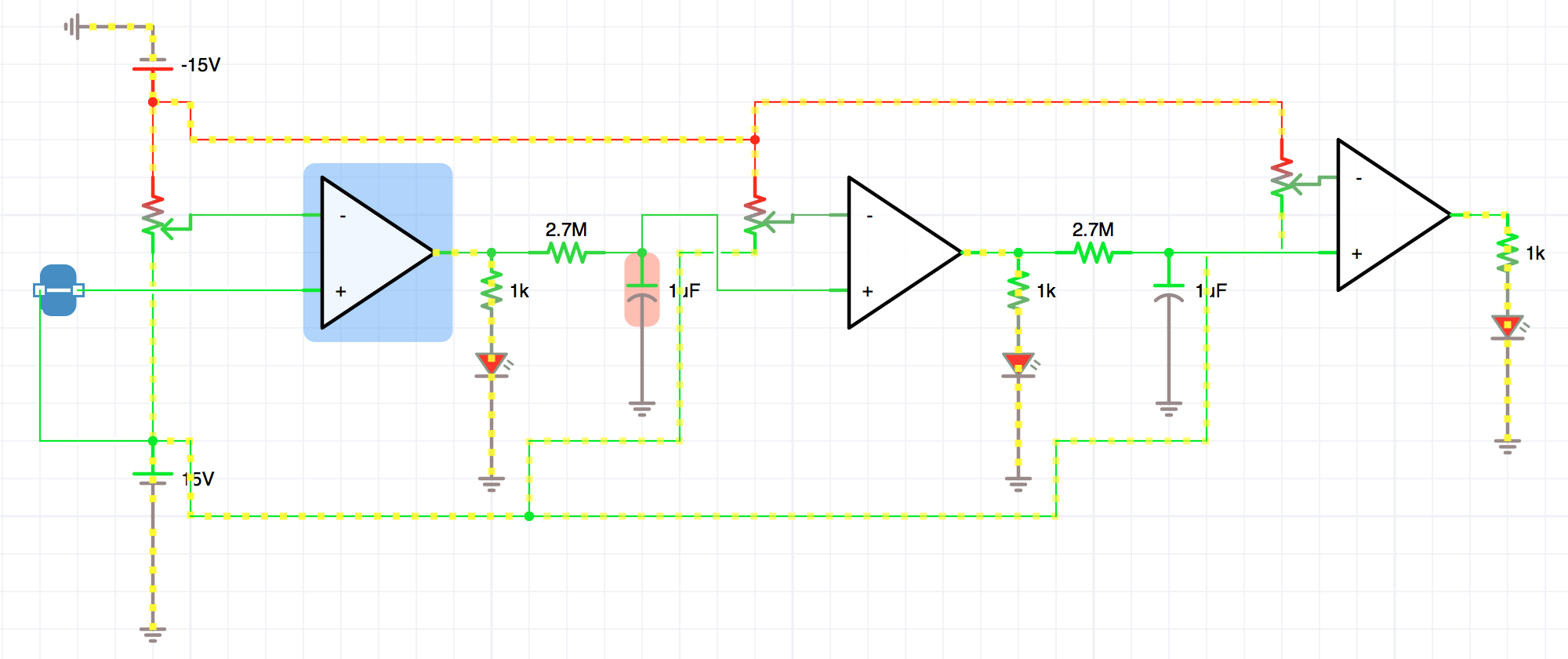
Figured it out, I kept trying to use these 'DC rail' components and was failing and getting errors I didn't understand. I switched to just basic DC sources and got it to work. Thanks for the suggestions, they got me thinking. Here's the circuit for anyone in the future who might be looking:

Timing circuit with comparators and capacitors

\$\endgroup\$

Your Answer

By clicking “Post Your Answer”, you agree to our terms of service and acknowledge you have read our privacy policy.

Not the answer you're looking for? Browse other questions tagged or ask your own question.