2
\$\begingroup\$

I am learning about gates, circuit diagrams etc. and I have been asked to create a 3 input NOR gate from NAND gates with 2 inputs.

Well, I know how to create a normal NOR gate with NAND gates, but I just ca'nt seem to grasp how I would get the 3rd input.

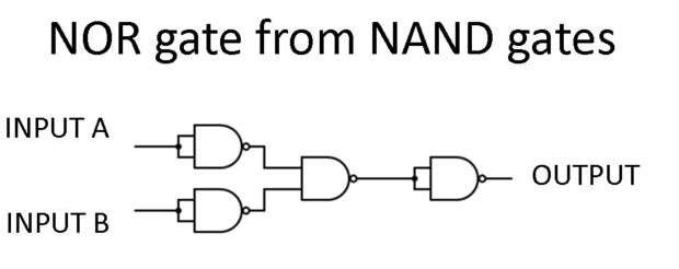
So the NOR with NANDS would be:

enter image description here

I didn't just look that up but I can't really draw my own, but I understand how that works, and I checked it with the truth tables and with some inputs.

How would I now create a similar circuit but for a 3 input NOR gate, I don't even know where to start.

\$\endgroup\$
6
  • 2
    \$\begingroup\$ A good start would be to write out the truth table. I also suggest looking up DeMorgan's theorem which shows the equivalence between NOR and NAND. \$\endgroup\$ Commented Sep 14, 2015 at 12:09
  • \$\begingroup\$ i have written out the truth table for it, I just don't understand how I am supposed to get the 3rd input from two original ones. I have a decent understanding of normal circuit diagrams and making truth tables from them and even simplifying them but I just don't get how I can go from 2 input to 3 only using NAND. \$\endgroup\$
    – James
    Commented Sep 14, 2015 at 13:26
  • \$\begingroup\$ Make two 2 input gates and try cascading one onto the other - you will need an inversion at the cascade. \$\endgroup\$ Commented Sep 14, 2015 at 14:17
  • \$\begingroup\$ @Peter smith, would this be correct? i.imgur.com/gIJ0Myc.png it seems correct to me but it could be completely wrong. \$\endgroup\$
    – James
    Commented Sep 14, 2015 at 14:36
  • \$\begingroup\$ I have spent over 5 hours on this one question at this point and it must be something obvious im missing because I can't find any help for it online. \$\endgroup\$
    – James
    Commented Sep 14, 2015 at 14:44

3 Answers 3

2
\$\begingroup\$

I don't usually answer homework this completely, but as you seem at a loss as to where to start:

Consider a simpler starting point.

If I have a number of 2 input OR gates and wish to make a 3 input gate, then assuming input names of A, B and C, then connecting the A and B inputs to gate 1, connecting the output of this gate to gate 2 and putting input C on the other input of gate 2 achieves a 3 input gate.

Taking your NOR gate: 2 input OR and NOR gate

A very important point to note is that the OR term is available. To make a 3 input NOR then we will take 2 2-input OR gates and do a final inversion for NOR.

So here then, we have:

A 3 input OR and NOR gate

If the images are not that clear, the OR output for your 2 input gate is just before the final inversion; use two of these and then add the final inversion.

The inversion term can be confusing at first, but the key here is to understand that the non-inverted term is available; cascading the non-inverted terms and then adding the final output inversion achieves the requirement.

HTH

\$\endgroup\$
2
\$\begingroup\$

You just have to remember these: $$\begin{align} a+b & = \overline{a}\cdot\overline{b} \\ a\cdot b & = \overline{a}+\overline{b} \\ \end{align}$$

Plus of course:

$$\begin{align} \overline{a+a} & = \overline{a} \\ \overline{a+0} & = \overline{a} \\ \overline{a\cdot a} & = \overline{a} \\ \overline{a\cdot 1} & = \overline{a} \\ \end{align}$$

So for example a 3-input NOR gate is:

$$\begin{align} \overline{a+b+c} & = \overline{\left(a+b\right)+c} \\ & = \overline{\left(\overline{a}\cdot\overline{b}\right)+c} \\ & = \overline{\overline{\left(\overline{a}\cdot\overline{b}\right)}\cdot\overline{c}} \end{align}$$

Hope this helps

\$\endgroup\$
1
  • \$\begingroup\$ @Tom Carpenter. Thanks for the edits. Looks good now \$\endgroup\$
    – Alexxx
    Commented Sep 16, 2015 at 21:24
0
\$\begingroup\$

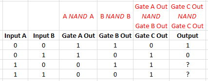
Just do each truth table for every gate. If you know the input, and know how a certain gate operates (NAND in this case) one can always compute the output. Repeat for each stage.

enter image description here

Starting with what I've labeled "Gate A" what if the input is 0, than both inputs to the NAND are 0, which means its output is 1. I've marked it in the chart. Repeat for an input of both 1's and repeat for gate B.

Now you have both inputs to gate C. Since you know the inputs to gate C you can write in the outputs of gate C for all states (Column C).

The red indicates the inputs and operation done to arrive at the output

Filling in the question marks should be pretty simple for column D. Know your inputs and logic; find your outputs. Draw a truth table.

Eventually you will start to use shortcuts such as the aforementioned Demorgan's theorem and things like recognizing if a NAND gate only has one input it simplifies to an inverter gate.

\$\endgroup\$

Your Answer

By clicking “Post Your Answer”, you agree to our terms of service and acknowledge you have read our privacy policy.

Not the answer you're looking for? Browse other questions tagged or ask your own question.