6
\$\begingroup\$

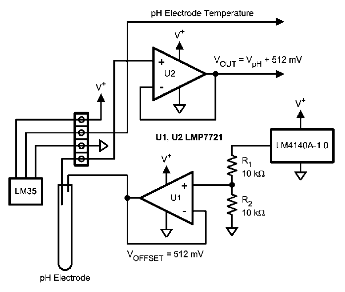
I am trying to build a pH meter using the below circuit.

I am trying to understand the function of Op Amp U1. As I understand it, the LM4140A-1.0 is a voltage reference outputting 1.024V, which is split into 0.512V by the voltage divider. This is fed into the Op Amp and through to the pH electrode where it offsets the voltage it generates (from -400mV to +400mV).

My question is, why do I need that unity-gain (buffer) op amp, why can I not just connect the 0.512V from the voltage divider into the pH electrode.

For completeness, I plan to take the high impedance output from the pH Electrode and pass it into a dedicated ADC, not the Op Amp U2 as described below, if this has any effect on the answer.

Image describing the circuit in question. http://www.national.com/an/AN/AN-1852.pdf

\$\endgroup\$
6
  • 1
    \$\begingroup\$ How high-impedance is your ADC? pH electrodes have very high output impedance, 50 to 500 MΩ according to wikipedia. You may want to keep the buffer amplifier in front of the ADC unless it has extremely high input impedance, like a GΩ. \$\endgroup\$
    – markrages
    Commented Oct 15, 2011 at 22:50
  • \$\begingroup\$ @markrages Thanks Mark, I shall be using this ADC ww1.microchip.com/downloads/en/DeviceDoc/22088c.pdf It has 25MΩ impedance. My pH probe is 300MΩ, what would I need to raise my ADC impedance too for this to be safe? What would happen if I used the ADC as is? \$\endgroup\$
    – James
    Commented Oct 15, 2011 at 22:58
  • 1
    \$\begingroup\$ if you use it as-is, you would form a two-resistor voltage divider, which will attenuate the voltage to less than one-tenth of the open-circuit voltage. (And that is assuming the ADC is a pure resistance and won't cause any signal distortions.) So a good buffer amp like the LMP7721 is necessary. \$\endgroup\$
    – markrages
    Commented Oct 15, 2011 at 23:03
  • \$\begingroup\$ You will need to be careful in construction to avoid leakage currents. Even fingerprints on the PCB can cause problems at these high impedances. If I recall correctly, there is a good discussion of pH probes in the Art of Electronics. And Bob Pease discusses measuring femto- and picoamps in one of his books. \$\endgroup\$
    – markrages
    Commented Oct 15, 2011 at 23:05
  • \$\begingroup\$ If it helps, U1 doesn't need to be a high-spec opamp. The only parameter that matters for U1 is input offset voltage. If your ADC is differential then use the output of U1 as the negative input to the ADC. That will cancel out R1 and R2 tolerance, and U1 offset voltage. \$\endgroup\$
    – markrages
    Commented Oct 15, 2011 at 23:08

6 Answers 6

6
\$\begingroup\$

Amplifier U1 helps to make the circuit as close to "ideal" as possible. In the pH cell the impedances involved re very high and any variations from ideality are reflected in the results.

The "challenge" is given in the following section from the application note:

  • The output of amplifier U1, which is set up in a unity-gain configuration, biases the reference electrode of the pH electrode with the same voltage, 512 mV, at low impedance.

    The pH-measuring electrode will produce a voltage which rides on top of this 512 mV bias voltage. In effect, the circuit shifts the bipolar pH-electrode signal to a unipolar signal for use in a single-supply system.

ie any error in this voltage is directly reflected in the output voltage as an error in pH reading.

The source impedance of the 2 x 10 k resistors in series is 5 K ( Reffective = R1 x R2 / (R1+ R2)). If the cell were to load this with a 1 megohm impedance the change in actual voltage would be 5k // 1 M = 0.005 = 0.5%. Loading with 10 Megohm would give 0.05% error etc. This does not sound much (& isn't much) but the sensitivity of the cell is 1 mV per pH. So 5/1000 x 512 mV ~= 2.5 mV or 2.5 pH error. And 10 megohm loading = 0.25 pH error. Even 100 megohm loading = 0.025 pH error.

If pH is read to even 0.1 pH units an error of 0.025 pH is 1/4 of a "bit". If pH was read to 0.01 units then 0.025 pH = 2.5 "bits " - and that's with 100 only megohm load!

Reducing R1 & R2 to 1 k or 100 ohms would help, at the expense of increased current drain U1 provides a better solution at acceptable cost.

\$\endgroup\$
2
  • \$\begingroup\$ I think I understand further now. I want to provide the pH electrode with 512mV at as low an impedance as I can manage. Assuming this is correct, if I were to have (theoretically) a battery outputting 512mV this could replace the U1 (just so I understand). \$\endgroup\$
    – James
    Commented Oct 15, 2011 at 20:30
  • \$\begingroup\$ @James - Yes, a "perfect" 512 mV battery would be perfectly fine. But any real world one would be a disaster. \$\endgroup\$
    – Russell McMahon
    Commented Oct 16, 2011 at 1:05
3
\$\begingroup\$

The LMP7721 opamp datasheet advertises with it's extremely low input bias current. The input bias current is the current going into the input terminals of an opamp. The ideal opamp model says that's zero, but it isn't in practice.

In most cases it isn't a problem. But you're dealing here with very high impedance sources. High impedance sources means you can't draw any current out of them. As I just said, an opamp draws current as well. Why would I bother?

Well, the pH electrode is probably very very high impedance (I expect mega ohms). The input impedance of a simple ADC of a PIC or AVR microcontroller is like 10k. If you imagine a voltage source, a resistor divider of 1M and 10k and connect the 'output' of that divider to the real sampler of the ADC, what voltages do you think you will measure? I think not a whole lot..

Also, if you draw 50nA through a 1MEG resistor, it causes a voltage (drop) of 50mV. This can be very significant.

This particular opamp has a huge input impedance. The error this opamp causes with it's input bias current is very very small. The opamp is able to provide enough current to drive your ADC.

The resistor divider of the reference is a similar story. 1uA load current on R1 will mean 10mV drop, which is over 2%! Using an opamp will solve this problem.

\$\endgroup\$
4
  • \$\begingroup\$ Most of your answer is about Op Amp U2, correct? My dedicated ADC will accept a high impedance input so that is okay. I am asking primarily about U1. Your saying the load on the top resistor of the voltage divider will affect the voltage that is output by it? \$\endgroup\$
    – James
    Commented Oct 15, 2011 at 20:24
  • \$\begingroup\$ I find it hard to believe your ADC has an input impedance as high as LMP7721. What ADC is it? \$\endgroup\$
    – markrages
    Commented Oct 15, 2011 at 22:58
  • \$\begingroup\$ My explanation goes to both stories. As Russel mentions, U1 is really only there to make it 'most ideal'. About the ADC, I thought I said an ADC of a simple microcontroller may be 10k or something similar. The LMP7721 has a much , much higher input impedance. \$\endgroup\$
    – Hans
    Commented Oct 16, 2011 at 17:37
  • \$\begingroup\$ What if remove voltage divider completely and connect lm4140 output directly? \$\endgroup\$
    – user30878
    Commented May 4, 2017 at 10:13
1
\$\begingroup\$

I don't know the physical configuration of the electrodes in your example, but the only situation where I could see much benefit to U1 would be if there were some source of current leakage into or out of the circuit, and most such leakage would be concentrated on the electrode tied to the op amp's output. For example, if there were a 100K leakage to ground from the signal that's now tied to U1's output, it would have little effect with the circuit as drawn. If, however, U1 were omitted, that 100K leakage would reduce the 512mV baseline voltage by about 5%. That could cause a severe error in the calculations.

If the physical configuration of the electrodes is such that leakage will be concentrated on the right one, the circuit as drawn could be very useful. Otherwise I'll admit I don't see much purpose.

\$\endgroup\$
1
\$\begingroup\$

U1 is in a configuration know as voltage follower or buffer. It just makes Vout= Vin, but with the advantage that it can provide any current value, positive or negative (within limitations). This means that it can source or sink any amount of current (within limitations).

In contrast, if you take the output directly of the divider node, any current flowing into or out of it will change its potential: it will not be a constant as you wish.

\$\endgroup\$
0
\$\begingroup\$

A low-impedance reference electrode supply is required, so that the voltage drop across the electrode-liquid interface is as low as possible.

\$\endgroup\$
1
  • \$\begingroup\$ Don't quite understand this Leon. I'm sure you've fully explained the answer in your sentence, however I'm unsure of the actual meaning. How does the low-impedance supply to the electrode (they are normally tied to GND when not biased) affect the voltage drop? If it is being driven to 512mv, surely that is the voltage drop? What does the impedance have to do with this? I can see I am missing something fundamental here... \$\endgroup\$
    – James
    Commented Oct 15, 2011 at 20:26
0
\$\begingroup\$

I was going to post a comment(especially since it's an old question), but it became too long.

That Application Note National AN-1852 (Which it located at TI now), describes in large detail the reasons for the inclusion of the op-amp to begin with.

It provides two totally different services to the circuit.

First it provides a low impedance 512mV bias to the sensor by buffering the output of the divided LM4140A-1.0 reference. * Side note, why go to the bother of calling for a 0.1% voltage reference, but then not denoting that the resistors should be at least 0.1% also? Maybe I've been spoiled by the LT, Analog and NatSemi App Notes(especially the older ones). * With out the op-amp it would distort the output wave forms. The same thing happens with some in-amps when a bare voltage divider is used for its reference input. For more information on why it happens, look at some the various notes on the usage of in-amps, such as this EDN Article, and this Maxim Article. At a later date the OP asked why not leave off the voltage divider all together. If you did so, your sensor would now be be provided with 1.024V, which may or may not be too much for the sensor;You may also need to redesign the input circuit to keep the input within the op-amps input range. To summarize, if you leave off the op-amp and use only the voltage divider, you'll get a distorted sensor reading. Please note, just about ANY op-amp could provide this service, as long as the divider output is within it's input range. It's a rare op-amp that would not provide sub-ohm output impedance at DC(if using feedback that is). This answers the original question.

Second it provides a high impedance input with a very low bias current. While the OP noted his specific ADC could be used with high impedance sensors, that is not even close to being all that is required. In single ended mode it has a input impedance of 25M ohms, compared to the sensors 200M+ output. That alone would reduce the output voltage by 1/8. Now when you take into account the various leakages the ADC would present, any chance at accuracy goes out the window. Which is why you want the op-amp in the circuit. Any, even semi-decent, CMOS op-amp will have an input impedance of over 1G ohm if not much greater. This means, in general, you can ignore it's effects on the signal. As far the input bias current goes(which is in essence the current being pulled from the sensor ), even a much older CMOS op-amp such as the LMC660 from 1998(I'm sort of cheating here, that op-amp is one of the greats in this area) has a input bias current of only 2-2000 fA max. That ADC has a input leakage of +/- 1 uA, an amount at least a million times worse than the op amp. Again, this would lead to distortion.

Now mind you, to take advantage of these stats to their full effect requires paying attention to detail. Like a prior answer said, at these levels, even finger prints make difference, some times reducing the advantages the op-amp brings to the table by more than an order of magnitude. This means guard rings, isolation and more.

Ops, this turned out much longer than I thought it would.

\$\endgroup\$

Your Answer

By clicking “Post Your Answer”, you agree to our terms of service and acknowledge you have read our privacy policy.

Not the answer you're looking for? Browse other questions tagged or ask your own question.