I was going to post a comment(especially since it's an old question), but it became too long.
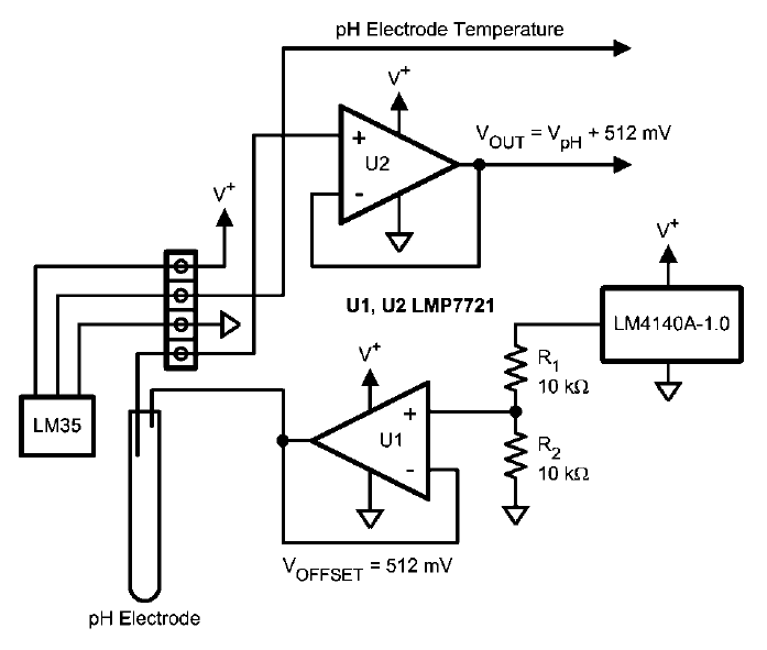
That Application Note National AN-1852 (Which it located at TI now), describes in large detail the reasons for the inclusion of the op-amp to begin with.
It provides two totally different services to the circuit.
First it provides a low impedance 512mV bias to the sensor by buffering the output of the divided LM4140A-1.0 reference. * Side note, why go to the bother of calling for a 0.1% voltage reference, but then not denoting that the resistors should be at least 0.1% also? Maybe I've been spoiled by the LT, Analog and NatSemi App Notes(especially the older ones). *
With out the op-amp it would distort the output wave forms. The same thing happens with some in-amps when a bare voltage divider is used for its reference input. For more information on why it happens, look at some the various notes on the usage of in-amps, such as this EDN Article, and this Maxim Article.
At a later date the OP asked why not leave off the voltage divider all together.
If you did so, your sensor would now be be provided with 1.024V, which may or may not be too much for the sensor;You may also need to redesign the input circuit to keep the input within the op-amps input range. To summarize, if you leave off the op-amp and use only the voltage divider, you'll get a distorted sensor reading. Please note, just about ANY op-amp could provide this service, as long as the divider output is within it's input range. It's a rare op-amp that would not provide sub-ohm output impedance at DC(if using feedback that is).
This answers the original question.
Second it provides a high impedance input with a very low bias current. While the OP noted his specific ADC could be used with high impedance sensors, that is not even close to being all that is required. In single ended mode it has a input impedance of 25M ohms, compared to the sensors 200M+ output. That alone would reduce the output voltage by 1/8. Now when you take into account the various leakages the ADC would present, any chance at accuracy goes out the window. Which is why you want the op-amp in the circuit. Any, even semi-decent, CMOS op-amp will have an input impedance of over 1G ohm if not much greater. This means, in general, you can ignore it's effects on the signal. As far the input bias current goes(which is in essence the current being pulled from the sensor ), even a much older CMOS op-amp such as the LMC660 from 1998(I'm sort of cheating here, that op-amp is one of the greats in this area) has a input bias current of only 2-2000 fA max. That ADC has a input leakage of +/- 1 uA, an amount at least a million times worse than the op amp. Again, this would lead to distortion.
Now mind you, to take advantage of these stats to their full effect requires paying attention to detail. Like a prior answer said, at these levels, even finger prints make difference, some times reducing the advantages the op-amp brings to the table by more than an order of magnitude. This means guard rings, isolation and more.
Ops, this turned out much longer than I thought it would.

