1
\$\begingroup\$

enter image description here

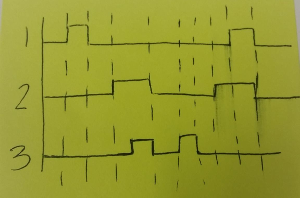
Hi :) I was wondering if I could have some help with figuring out what circuit would yield this waveform. I'm trying to make sure that 1 and 3 can only be high if 2 is high when they are triggered. I'm unsure of how to:

a) hold 2 high and have it drop when the signal from 1 or 3 ends (it will be a blip from a button)

and

b) have 1 and 3 be ignored when 2 is not high

I was thinking about potentially using a clocked t-flip-flop but I have minimal experience in pretty much all things EE.

Thanks for your help :)

\$\endgroup\$
9
  • 6
    \$\begingroup\$ A microcontroller can do that \$\endgroup\$
    – PlasmaHH
    Commented Feb 25, 2016 at 21:22
  • \$\begingroup\$ @PlasmaHH What would I be programming it to do? I have a National Instruments DAQ system I could use if you think that may be applicable. \$\endgroup\$ Commented Feb 25, 2016 at 21:25
  • \$\begingroup\$ In your 4th time period you seem to have 3 half low & half high. Should that be split into 2 time periods with 3 low in one and high in the other and 2 high for both of them? \$\endgroup\$
    – brhans
    Commented Feb 25, 2016 at 21:30
  • \$\begingroup\$ @MadisonLilly: Welcome to SE. You could have cropped your photo for us. ;^) I think you should have six waveforms on your sketch. IN1, OUT1, IN2, OUT2, IN3 and OUT3. If you do this it will help clarify your thinking. You then should be able to do what you want with set/reset latch, inverters and AND gates. \$\endgroup\$
    – Transistor
    Commented Feb 25, 2016 at 21:33
  • \$\begingroup\$ @brhans yes, oops :/ thanks for spotting that. and thanks transistor, I'll crop next time and try the ins and outs. Can't believe I didn't think to include those :) \$\endgroup\$ Commented Feb 25, 2016 at 21:35

1 Answer 1

1
\$\begingroup\$

As a first try, I recommend you use 2 AND, 1 OR, and an edge-triggered D type flip-flop. Connect signals 1 and 2 to input of one AND, 2 and 3 to inputs of other AND. Connect the outputs of the AND gates to inputs of OR gate. Connect output of OR gate to reset pin of flip-flop. Connect output of flip-flop to set pin of flip-flop and to the signal 2 inputs of the AND gates. Connect the clk signal to the flip-flop.

\$\endgroup\$

Your Answer

By clicking “Post Your Answer”, you agree to our terms of service and acknowledge you have read our privacy policy.

Not the answer you're looking for? Browse other questions tagged or ask your own question.