0
\$\begingroup\$

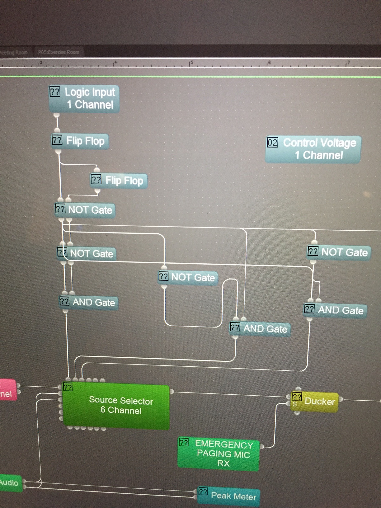
I was in a training class and the instructor went quickly over how to use a single output momentary switch to effectively drive 4 different states, which he didn't think was important and skimmed--so that on each push (assuming you're starting with all inputs low) you get something like 1000, 0100,0010,0001, and then start over. I took a snapshot (below) of the screen that we were using, but I'm a bit confused as to the route we took using the flip flops and logic gates. His also seemed a buggy, so i'm wondering if using AND/OR/NOT and flip flops if there is a more efficient way to do this?

1) Is this technically a binary counter 2) Its not clear how to break think about this, as his way seemed super convoluted and didn't always work correctly, particularly at resetting the 4th state to the first.

enter image description here

\$\endgroup\$

2 Answers 2

2
\$\begingroup\$

It is not a full digital counter, as it has 4 bits which may hold up to 16 different patterns but only 4 are used.

What your instructor attempted to do was to take a 2-bit binary counter using two flipflops, then use a superfluous amount of NOT gates together with some ANDs to let each AND gate react to exactly one pattern out of the possible four (in essence a binary decoder).

What you are really looking at is a shift register. You can construct it using 4 edge-triggered flipflops, where the output of each flipflop is connected to the iput of the next, and the last one is looped back to the first. Each transition of the 'clock' signal will then move the contents of each flipflop to the next. Getting those flipflops in the initial '1000' state requires some additional circuitry.

\$\endgroup\$
1
\$\begingroup\$

Each time the Logic Input turns on Flip Flop 1 (FF1) changes state. That gives us this table:

In | Out
0  |  0
1  |  1
0  |  1
1  |  0
0  |  0    etc.

This in turn feeds FF2 so now we get

In | FF1 | FF2
0  |  0  |  0
1  |  1  |  1
0  |  1  |  1
1  |  0  |  1
0  |  0  |  1
1  |  1  |  0
0  |  1  |  0
1  |  0  |  0
and back to the start ...

Just looking at FF1 and FF2 changes you can see they will run the pattern

FF1 | FF2
 0  |  0
 1  |  1
 0  |  1
 1  |  0

That gives you four combinations. With some AND and NOT you can manipulate these into the desired sequence.

I'm not familiar with the schematic system you have photographed and can not figure out what's happening on the right hand side, but I hope the information above is enough to get you on your way.

\$\endgroup\$
2
  • \$\begingroup\$ @transistor--I think I expected the input 1 to initially make FF1 = 1, so then I was confused by the logic being staggered. But how could do something similar to end up with 4 discrete logic states given a single input? \$\endgroup\$
    – inbinder
    Commented Feb 25, 2016 at 23:43
  • \$\begingroup\$ I assumed that the 6-channel source selector is using a binary system to select the channels. If so, then my last table shows how to select one of four channels. If not JvO may be on the right track. How many channels are there in use? \$\endgroup\$
    – Transistor
    Commented Feb 26, 2016 at 0:02

Your Answer

By clicking “Post Your Answer”, you agree to our terms of service and acknowledge you have read our privacy policy.

Not the answer you're looking for? Browse other questions tagged or ask your own question.