2
\$\begingroup\$

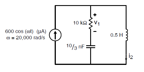
I'm trying the find the current (using phasors) through the inductor shown below.

Using the current divider rule, I got that 840+j480 uA are going through the inductor. Additionall, by Kirchoff's laws and the terminal relationships of the resistor, capacitor, and inductor, I got the same answer.

My issue is that the magnitude of the current entering the circuit is 600 uA, but the magnitude of the current through the inductor is 967.471 uA which exceeds the source current. This is not allowed, correct?

Where did I go wrong?

enter image description here

\$\endgroup\$

2 Answers 2

2
\$\begingroup\$

I guess your calculations are ok. You have an opposite current through the capacitor that partly cancels the current through the inductor.

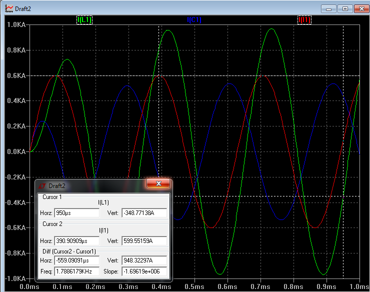
Since this is not so easy to see, I made a quick simulation:

The red trace is the source, the green one the current through the inductor and the blue one the current through the capacitor.

enter image description here

\$\endgroup\$
3
  • \$\begingroup\$ Why is the inductor current allowed to be greater than the current applied by the current source? Isn't this a violation of the conservation of current? \$\endgroup\$
    – user88062
    Commented Feb 27, 2016 at 17:05
  • 1
    \$\begingroup\$ It isn't greater. You also need to account for the phase relationship and calculate the net current. If you have a look at simulation you can see that the red trace is equal to the sum of the green and the blue trace. \$\endgroup\$
    – Mario
    Commented Feb 27, 2016 at 17:14
  • \$\begingroup\$ In a parallel tuned circuit (with zero resistance) at resonance, there will be zero total current, but equal magnitude currents (\$\small V/X_C\$ and \$\small V/X_L\$) in the C and the L, where \$\small V\$ is the supply voltage. The individual C and L currents are 180deg out of phase, so sum to zero. \$\endgroup\$
    – Chu
    Commented Feb 27, 2016 at 19:06
2
\$\begingroup\$

You seem to have in mind what you learned about DC circuits with resistors. There is some source that forces current through some resistors, and the current in each resistor can never exceed the current provided by the source, because the source current is divided among the resistors.

The key concept that makes this work for DC circuits is that pushing current into a circuit is equivalent to pushing energy into that circuit, which is something a passive component obviously cannot do. The point about the energy is still valid in AC circuit analysis, but there can be current sources that are not energy sources, if current and voltage are 90 degrees out of phase.

In your circuit, the current through the inductor is sourced from both the current source and the capacitor. On the other hand, if you calculate the energy consumed by the only lossy element in your circuit (the resistor), it should match the energy provided by the only energy source (the AC current source) exactly.

It is interesting to understand that the combination of an element with current and voltage in phase (the resistor in your circuit) and an inductor in series is how fluorescent lamp ballast circuits work (at least in 220V countries). In big industrial lighting installation, capacitors are paralleled to compensate for the inductance, so the impedance gets real. In this practically proven circuit, the lamp current (at 100V) exceeds the supply current (at 220 to 240 volts), so transmission losses between the utility company and the lighting installation is minimized.

\$\endgroup\$

Your Answer

By clicking “Post Your Answer”, you agree to our terms of service and acknowledge you have read our privacy policy.