0
\$\begingroup\$

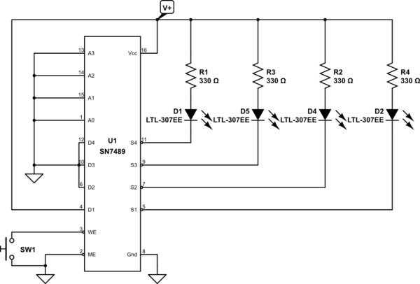
This is a follow up question to this question.

I have attempted to draw a schematics of my setup for the 7489 below. Without the switch closed, the LED D1 is on. Then the switch is closed, then also LED D5 comes on. If I connect the ME to high, then this behavior does not change. Also, if say D2 is brought high with the other inputs low, then all the LEDs are off.

Does this mean that I am doing something wrong, or have I broken the chip?

(I have also tried inserting pull up resistors (1kOhm to 4.7 kOhm) on the address inputs.)

schematic

simulate this circuit – Schematic created using CircuitLab

\$\endgroup\$
8
  • \$\begingroup\$ Thanks for cleaning up the schematics. It is my first time using this. \$\endgroup\$
    – Thomas
    Commented May 27, 2016 at 22:54
  • \$\begingroup\$ Please try changing the D1-D4 inputs to see if the LED's change their pattern. \$\endgroup\$
    – user105652
    Commented May 27, 2016 at 23:21
  • 1
    \$\begingroup\$ The IC is blown then. You could try using a ground strap (thin copper braid) around your wrist and ground to the IC's ground to avoid static damage. Other than wiring errors that is the number one cause of both LED and IC failures. \$\endgroup\$
    – user105652
    Commented May 27, 2016 at 23:46
  • 1
    \$\begingroup\$ Just for the record, I used a 7489 in 1978 quite successfully. Yeah I know It's irrelevant but what the hell! \$\endgroup\$
    – Andy aka
    Commented May 28, 2016 at 0:04
  • 1
    \$\begingroup\$ @Andyaka: Can you remember how you wired it up? :) \$\endgroup\$
    – Thomas
    Commented May 28, 2016 at 0:08

2 Answers 2

1
\$\begingroup\$

This is a memory IC, so it remembers the state of D1-D4 when ME is low and you pulse WE low. The leds that should be OFF are R1, R2, and R3. R4 should be ON.

To change which LED's are ON you need to change the state of the memory inputs (D1-D4), then bring WE low then high again and see the change.

The data outputs of this IC are inverted, so to turn an LED 'ON' you need to connect the corresponding input to V+. Your only using address '0' (A0 - A3 are low), so toggling the ME pin has no effect. If it is high (V+), it will disable any changes to the memory, but not affect existing memory and the outputs.

The pdf sheet on this part specifies a load of -12mA as being a safe maximum load, as a current sink. At 330 ohm's the LED current is only 6mA. If the IC's output is irrational then it is oscillating or it is blown. Add a .1uF capacitor to the power pins and a 10K pull-up resistor to the WE pin for stability.

If you turn off the power this memory will forget its contents and all LED's should be OFF.

\$\endgroup\$
10
  • \$\begingroup\$ Thanks for the answer. If I connect all the inputs to V+ then I get all the same pattern. \$\endgroup\$
    – Thomas
    Commented May 27, 2016 at 23:25
  • \$\begingroup\$ Also, as I read the datasheet, all LEDs should be off when /WE is low (all outputs should be high). \$\endgroup\$ Commented May 27, 2016 at 23:25
  • \$\begingroup\$ @PeterBennett: That is what I was thinking. So maybe (assuming that I am doing everything right) the conclusion/answer is that the IC is broken? \$\endgroup\$
    – Thomas
    Commented May 27, 2016 at 23:27
  • \$\begingroup\$ @PeterBennett. Not with D1 connected to V+. The outputs are inverted OC type. At present only D2 should be on. I need to check the sink current for this IC. It may not be able to drive LED's directly. \$\endgroup\$
    – user105652
    Commented May 27, 2016 at 23:29
  • \$\begingroup\$ Maybe I should add that if, say, D2 is brought high with the other inputs low, then all the LEDs are off. \$\endgroup\$
    – Thomas
    Commented May 27, 2016 at 23:31
0
\$\begingroup\$

You have all of the address pins constantly held low giving the address 0000, you have all of the data bits held low except for bit 1 giving a nibble (or word in the datasheet) of 0001. Using !ME and !WE (to replace the overscore notatation used for active low in the datasheet) - you have !ME always low, and (hopefully) can toggle !WE low by closing the switch - it might be worth pulling this high with a resistor when you're not trying to write, but that might be irrelevant - at the moment you've got two possible control states: !ME Lo !WE Hi, and !ME Lo and !We Lo, the truth table on the data sheet says that if both are low (the state when you have the switch closed), all data outputs will be Hi. If !ME alone is lo and !We is Hi, then you'll be in read rather than write mode, and the four outputs will show the COMPLIMENT of the inputs for the nibble you're addressing (since you've got a fixed address and a fixed input of 0001, you should see a fixed output of 1110) - so you shouldn't really see any change between holding the button or not except in the diode attached to S1 - taking !ME high should leave outputs high. When you say LED1, do you mean LED 1 in your schematic (attached to S4) or do you mean D2 (attached to S1)? Ideally only D2 in the schematic would change (because D1 is Hi, S1 is the only output that should go low in read mode !ME lo !We Hi), if you're in write mode (both controls !ME and !WE lo) then all outputs should be high, as they should be if you take !ME high regardless of the !WE state - and if they're high they shouldn't be able to light the LEDs
\$\endgroup\$
5
  • 1
    \$\begingroup\$ Hint: You will have better chance of up-votes if you break up your wall of text into small paragraphs. \$\endgroup\$
    – user105652
    Commented May 27, 2016 at 23:49
  • \$\begingroup\$ ;) not used to this formatting - it doesn't read fluently, you're right \$\endgroup\$
    – RayHicks
    Commented May 27, 2016 at 23:52
  • \$\begingroup\$ also, I though ti was commenting not trying to answer - any hints on that? I'm ure I hit comment, but it's not in the comment line \$\endgroup\$
    – RayHicks
    Commented May 27, 2016 at 23:53
  • \$\begingroup\$ Very long comment. In fact it would have been cut short with a "Too many characters" warning. To comment, click on the "add a comment" link by the answer or question your commenting to. Use the '@' symbol to find names in a long list of comments so that person gets the comment sent to them. \$\endgroup\$
    – user105652
    Commented May 28, 2016 at 0:10
  • \$\begingroup\$ Yeah I'm new to writing on this, having leeched much info in the past. I got carried away that I might be able to help - so carried away that I didn't see you'd put in a more succinct answer before I sent in my blurb:) - thanks for the tips \$\endgroup\$
    – RayHicks
    Commented May 28, 2016 at 0:28

Your Answer

By clicking “Post Your Answer”, you agree to our terms of service and acknowledge you have read our privacy policy.

Not the answer you're looking for? Browse other questions tagged or ask your own question.