2
\$\begingroup\$

I am using a MCP79410 real time clock to generate a 1Hz square wave signal (50% duty cycle) for a low power display (Sharp Memory LCD). Without this signal charge builds up and the pixels show burn-in.

The problem is that the RTC output is open-drain, so a pull-up resistor is needed. Because I need to save power I cannot use a resistor smaller than ~1MOhm. Unfortunately with this resistor the display does not recognize the signal anymore, 10kOhm works perfectly fine. Now my guess would be, that this is due to the slow rise time of the signal. The frequency and duty cycle don't have to be very accurate.

What would be the most simple way to solve this?

Maybe a (schmitt trigger) inverter could improve the edges of the signal.

EDIT: I soldered a Schmitt trigger inverter (74HC1G14) onto the board. It works!! Thanks for your help!

Overall power consumption in standby is under 10uA now. I can't say much about the dynamic consumption but it should be OK. For the final design I might switch to the SN74AUP1T14 as user2943160 suggested.

enter image description here

\$\endgroup\$
6
  • \$\begingroup\$ Assuming the rise/fall time is the root cause, a schmitt trigger should be a usable solution. Also, check your input/output/stray capacitances on that line vs. signal timings at that 1Mohm. I wouldn't expect pro lems @1hz, but if your waveform is closer to DC with a single short-duration pulse every second then you'll have to use the (much higher) frequency of that pulse for your calculations. In that case, the 1Mohm may simply be too high for proper signalling. \$\endgroup\$ Commented Jul 9, 2016 at 15:19
  • 1
    \$\begingroup\$ Thanks for the answer. The signal is basically a 1Hz square wave with 50% duty cycle, so the pulse is 500ms long. I have schmitt trigger inverters lying on my desk, just need solder one in and test if it works. \$\endgroup\$
    – MaxMKA
    Commented Jul 9, 2016 at 15:25
  • \$\begingroup\$ From st2000's answer, can you provide the datasheet for the RTC being used? \$\endgroup\$ Commented Jul 9, 2016 at 15:57
  • \$\begingroup\$ Of course: ww1.microchip.com/downloads/en/DeviceDoc/20002266F.pdf \$\endgroup\$
    – MaxMKA
    Commented Jul 9, 2016 at 16:00
  • \$\begingroup\$ @MaxMKA Please edit the link into the question text. Comments aren't permanent on SE sites. \$\endgroup\$ Commented Jul 9, 2016 at 17:19

3 Answers 3

3
\$\begingroup\$

You don't say what signal it is you are driving, but most of the inputs in the datasheet you linked to specify a maximum rise time of 50ns. The larger resistor and any input capacitance will certainly exceed this rise time requirement.

A simple CMOS buffer will help by squaring up the edges as it has a much higher drive strength than the pull-up resistor.

The key is to find one with a low input capacitance which will allow you to use a higher resistance pull-up which while keeping the rise time at the input of the buffer reasonable.

As an example the SN74LVC1G34 has an input capacitance of around 3pF. Even with that low of a capacitance, you are still looking at a 2-3μs rise time at the buffer input. This may well be acceptable, but as you can see, it is still very slow.

You can also use a Schmitt trigger. That will mean that if there is a very long rise time on the input signal you will have better noise immunity to stop the output toggling at high frequency during the transition. But again, you need to make sure the input capacitance is minimised.

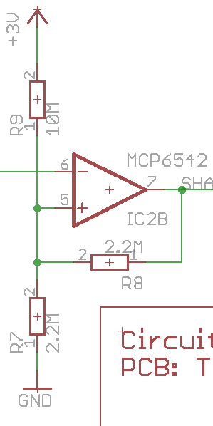
Another alternative would be to get an ultra-low power comparator. Microchip do some nano-amp comparators. I've used some of these in the past coupled with 10MΩ bias resistors to create a low power draw Schmitt trigger for a coin cell application. The whole circuit including resistors draws less than a 1μA (it was too low for the ammeter I was using to measure). You can tune the resistors to match the required hysteresis, but this was the circuit I used in that application:

Comparator Schmitt Trigger

\$\endgroup\$
7
  • \$\begingroup\$ If the rise / fall times are slow, a trigger is probably necessary to prevent long term damage to the internal devices. \$\endgroup\$ Commented Jul 9, 2016 at 15:23
  • \$\begingroup\$ @PeterSmith indeed, though that is where the comment about low capacitance comes in. If the input capacitance of the buffer is low, the pull up resistor can be larger while still maintaining reasonable rise times. \$\endgroup\$ Commented Jul 9, 2016 at 15:25
  • \$\begingroup\$ Thanks. The signal is basically just a square wave. I will definitely try the schmitt trigger solution as I already have those at hand. \$\endgroup\$
    – MaxMKA
    Commented Jul 9, 2016 at 15:32
  • \$\begingroup\$ Would it be possible to create a schmitt trigger oscillator based on your comparator? I originally wanted to use an oscillator with a regular schmitt trigger as a source for the 1Hz signal. But these devices draw a lot of power when the input voltage is something in the middle between 0 and VCC. \$\endgroup\$
    – MaxMKA
    Commented Jul 9, 2016 at 15:51
  • \$\begingroup\$ Note that the \$\Delta I_{CC}\$ is up to 500µA during signal transition on the SN74LVC1G34 (page 7, section 7.5). \$\endgroup\$ Commented Jul 9, 2016 at 15:56
3
\$\begingroup\$

You want to find a CMOS buffer with extremely low quiescent current. Changing to a logic gate will not do you much good if the leakage current of the transistors in your buffer/inverter draws significantly more current than the 1M pull-up resistor.

Use of a Schmitt trigger input is probably advised due to the very slow rise time of the input signal. This will also help avoid additional power consumption due to the input of a 'normal' logic gate spending a long time at an invalid logic level. Since your signal polarity doesn't matter to the display, using an inverter is a completely valid option.

One such Schmitt trigger, 3.3V compatible, low quiescent current option is the SN74AUP1T14 inverter. There will probably be a fair number of footprint-compatible options you can research.

\$\endgroup\$
1
\$\begingroup\$

Low power battery operated designs can be very difficult. A good knowledge of hardware is often necessary to identify potential problems and how to fix them. And always step back and consider alternative solutions. For instance, perhaps the Microchip RTC can be programmed to have a short low duty cycle. Thereby mitigating the problems associated with a small valued pull up resistor. Perhaps the signal only needs to be sharp on the rising edge of the signal. Using a transistor to the positive rail and a large pull down resistor may provide such a wave form.

\$\endgroup\$
1
  • \$\begingroup\$ The transistor is an interesting idea. I don't think there are many more settings for the rtc. The alarm pin would be another source for a 1 second interrupt, but it is open drain as well and needs to be reset using an I2C command. \$\endgroup\$
    – MaxMKA
    Commented Jul 9, 2016 at 16:02

Your Answer

By clicking “Post Your Answer”, you agree to our terms of service and acknowledge you have read our privacy policy.

Not the answer you're looking for? Browse other questions tagged or ask your own question.