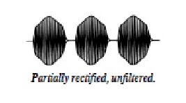
From the way you've described your waveform you have a voltage as a function of time that looks something like,
$$
v(t) = 235\sin\left(\frac{2\pi t}{T}\right)\left[ u(t) -u(t - 0.85T) \right] \quad t\in[0,T].
$$
For the RMS voltage calculation you then get:
$$
V_{RMS}^2 = \frac{1}{T} \int_0^T 235^2\sin^2\left(\frac{2\pi t}{T}\right)\left[ u(t) -u(t - 0.85T) \right]^2dt \\
= \frac{235^2}{T} \int_0^{0.85T}\sin^2\left(\frac{2\pi t}{T}\right)dt \\
= \frac{235^2}{T} \int_0^{0.85T} \left(\frac {1-\cos\left(\frac{4\pi t}{T}\right)}{2}\right) dt \\
= \frac{235^2}{T}\left[ \frac{0.85T}{2} - \frac{T}{8\pi}\sin\left(0.85\cdot4\pi\right)\right] \\
=235^2\left[\frac{0.85}{2}-\frac{\sin\left(0.85\cdot4\pi\right)}{8\pi}\right].
$$
Then you'll have,
$$
V_{RMS} = 235\sqrt{\frac{0.85}{2}-\frac{\sin\left(0.85\cdot4\pi\right)}{8\pi}}\approx 160~\text{V}.
$$
So for your power calculation then,
$$
P = \frac{V_{RMS}^2}{R}=\frac{160^2}{500}=51.2~\text{W}
$$
I hope this makes it clear that for more complex waveforms calculating the RMS voltage is not quite as simple as it is for "nice" sinusoids. What's worse about this waveform is that the RMS voltage depends on whether or not you base your waveform on a sine or cosine waveform!
Update:
It looks like the waveform you are supplying is both amplitude and duty cycle modulated, you can follow the same procedure to find the RMS voltage of your actual waveform. You may have to do this over a number of periods (until the modulating and modulated sinusoids are harmonics of each other). Your new waveform is something like,
$$
v(t) = 235m\sin\left(\frac{2\pi t}{T_1}\right)\sin\left(\frac{2\pi t}{T_2}\right)\left[u(t) - u(t - 0.85T_1\right],
$$
where in this case the waveform with period \$T_1\$ is the modulating waveform with modulation index \$m\$.
 The waveform looks like as shown. It has hf sinusoidal oscillation in active part.