1
\$\begingroup\$

I recently made a circuit using the ttl 7400 NAND gate IC. The concept is simple. There are two 4 bit inputs going into the 7400 IC. The 7400 IC does a 4 bit NAND operation on these bits, and outputs them. The outputs are used to drive 4 LED's(each LED represents one bit). I made the circuit and it does nothing. The LED's are all off when all input bits are LOW. If I change the input bits nothing happens. Here is a chart to sumarize the behavior of the circuit I built:

enter image description here

As you can see, no matter what the input the outputs is always 0000.

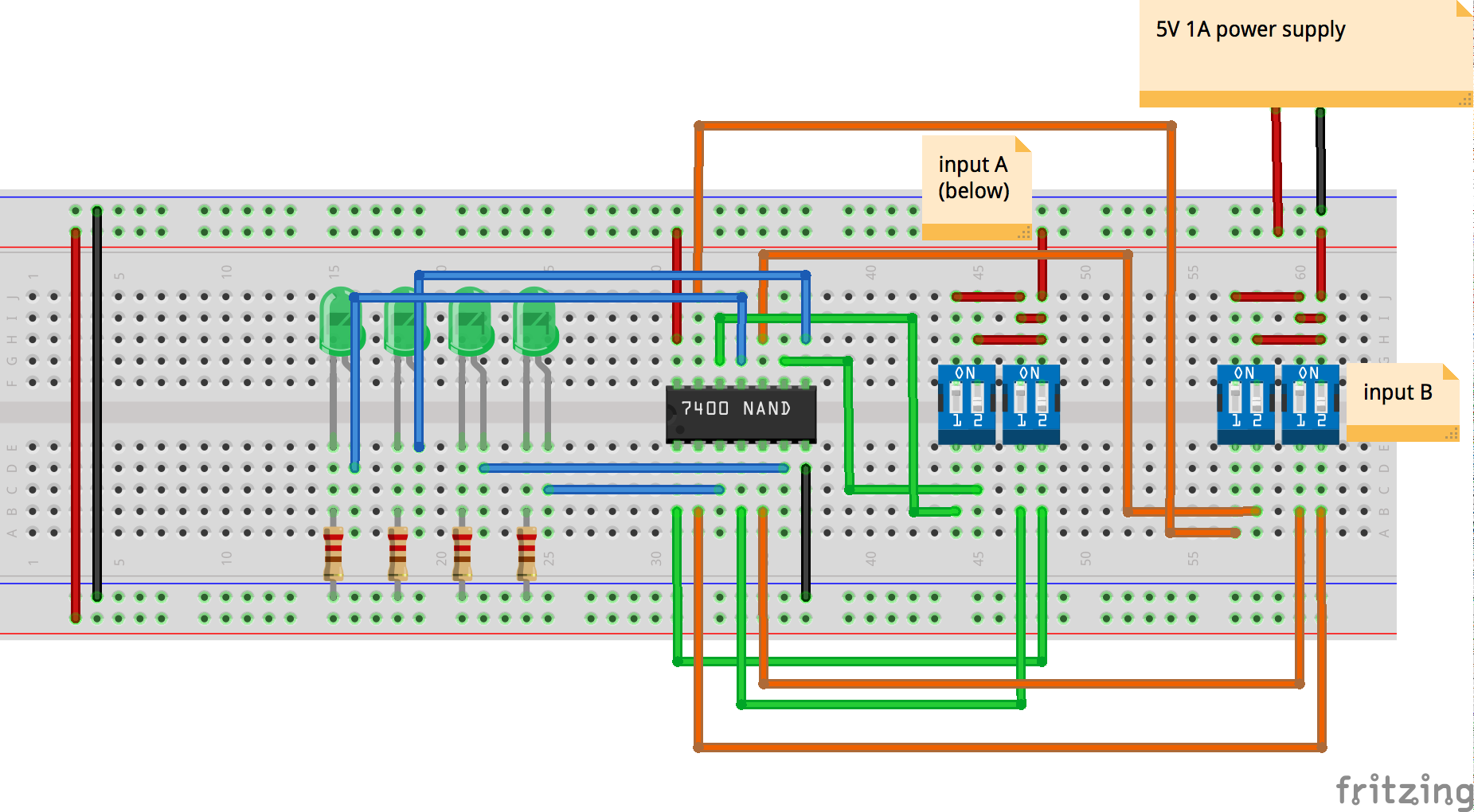
Here is a diagram of the circuit:

enter image description here

Here is the data sheet of the 7400 IC(I'm not sure who manufactured the chip but it says 7400N on it): http://www.ti.com.cn/cn/lit/ds/symlink/sn74ls00.pdf

(The top left diagram on the data sheets first page is the 7400's pinout diagram)

\$\endgroup\$
9
  • 4
    \$\begingroup\$ Draw a proper schematic (a fritzing diagram of a breadboard is not a schematic) and also upload a picture of your circuit. \$\endgroup\$ Commented Jul 19, 2016 at 23:17
  • 4
    \$\begingroup\$ If your breadboard is a double length one like shown, remember that typically there is a break in the power rail at the centre point, so it is possible that the GND and VCC are not connected to your NAND. But without an actual photo that is a guess. \$\endgroup\$ Commented Jul 19, 2016 at 23:18
  • 5
    \$\begingroup\$ Also you are not connecting your inputs properly. You are connecting them to switches so that the inputs are either connected to VCC or left floating. A 7400 series TTL device like the one you have has internal pull ups, which means when floating the pins will pull high - basically all your inputs are always high. Your switches should connect to GND. \$\endgroup\$ Commented Jul 19, 2016 at 23:20
  • 3
    \$\begingroup\$ Makes sense. If you invert both inputs of a NAND gate, you get an OR gate. Now that when the switches are pressed the input is a zero - so you need to remember that closed = 0, open = 1. I'll write all this up as an answer in a little while, just having dinner. \$\endgroup\$ Commented Jul 20, 2016 at 0:04
  • 1
    \$\begingroup\$ Just treat the switch being closed as a 0. You don't need any extra circuitry - the inversion can be built into your head with no electronics required. \$\endgroup\$ Commented Jul 20, 2016 at 4:01

1 Answer 1

3
\$\begingroup\$

The LED's are all off when all input bits are LOW

No, your input bits are never low. When a switch is ON it connects +5V to an input. When the switch is OFF it connects nothing, and the input is 'floating'. Floating is not LOW. In TTL logic, LOW is a voltage between 0V and 0.8V (see datasheet page 4, "VIL Low-level input voltage").

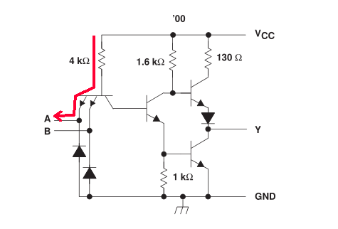
Perhaps you thought that with nothing connected the input would naturally go down to 0V. But it won't, because the input circuit of a TTL NAND gate looks like this (datasheet page 3):-

enter image description here

I added a red line to show how voltage gets from Vcc to the input pin. With nothing connected the input will float at about 1.8V. To make the input LOW you must sink the Input Low current (IIL, datasheet page 4) by pulling the input below 0.8V.

There are two ways to pull an input LOW with a switch. One way is to connect a pull down resistor from the input to ground. Since IIL can be up to 1.6mA, and the voltage across the resistor needs to be less than 0.8V, the resistance value must be less than 0.8V/1.6mA = 500Ω. This method has the disadvantage that when the switch is ON it puts 5V across the resistor, which wastes current.

The other way is to connect the switch to Ground rather than +5V, then switch ON = LOW. Since TLL inputs float high you may get away with just doing this, but to produce a properly defined HIGH (>=2.4V) you should add a pull up resistor to Vcc. Input High current (IIH) is only 40uA, so a large value resistor will do, eg. 10KΩ. There is still some wasted current, but much less than with a pull down resistor.

\$\endgroup\$
1
  • \$\begingroup\$ Used the first method you described using 220Ω resistors and it worked perfectly. Thanks. \$\endgroup\$
    – zack1544
    Commented Jul 27, 2016 at 0:07

Not the answer you're looking for? Browse other questions tagged or ask your own question.