1
\$\begingroup\$

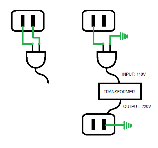
In the diagram below, the image on the left shows how a plug is normally connected to an outlet.

The image on the right shows how the socket is replaced by a new configuration. One of the holes on the original socket is used and connected to a transformer, while the other plug is connected to the ground to create a circuit. The rationale for this is: when I used a voltmeter to connect the socket to the ground, I was able to read 110V. Clearly, there is some voltage you can draw from just one hole of the socket.

The voltage is run through a step up transformer, creating 220V. This is used to create a new socket. One of the holes is connected to the ground, while the other one is live.

This entire setup clearly looks incorrect to me, but I don't know the specific reasons why. I created a setup that looks roughly like this (using a voltage regulator for the new socket, and using a long line to plug the wire in cemented ground far away from me) and it was able to charge a power bank, but it couldn't drive an electric fan forward -- the blades started spinning, but very very slowly. There were no fires or electric shocks experienced by anyone.

But, I don't understand why the setup worked in the first place. It seems to me like it shouldn't have worked at all.

My question is, What is wrong with this design, and why did it sort of work?

sockets

\$\endgroup\$
5
  • 1
    \$\begingroup\$ How on earth (pun accidental but intended) did you manage to connect the transformer up using only one wire? \$\endgroup\$
    – pipe
    Commented Sep 24, 2016 at 9:13
  • \$\begingroup\$ @pipe The transformer is a small device that came with a plug. I just took copper wires and electric tape to connect them in the fashion you see in the right diagram. \$\endgroup\$ Commented Sep 24, 2016 at 9:16
  • 1
    \$\begingroup\$ I guess I still don't completely get it, and I'm not terribly interested in trying to solve the puzzle but see if this article about single-wire earth return helps. \$\endgroup\$
    – pipe
    Commented Sep 24, 2016 at 9:17
  • \$\begingroup\$ Much more detail on connections and actual transformer etc used. \$\endgroup\$
    – Russell McMahon
    Commented Sep 24, 2016 at 9:34
  • 1
    \$\begingroup\$ It's great that you want to experiment to improve your understanding! However, if your understanding of how electricity flows in circuits is incomplete, you should find something safe to experiment with. Mains electricity is not that; one mistake in your understanding can kill you. Please use low voltages to experiment, at least until you really understand these things. And preferably even after that. \$\endgroup\$
    – marcelm
    Commented Sep 24, 2016 at 10:16

2 Answers 2

3
\$\begingroup\$

Earthing or grounding is designed to protect the users of electrical equipment by preventing dangerous voltages to appear on metal casings, etc.

schematic

simulate this circuit – Schematic created using CircuitLab

Figure 1. Building supply neutral is earthed / grounded at the supply transformer.

In most countries the electrical utility grounds one of the wires from the local step-down transformer. This "neutralises" the wire as there is now no potential relative to earth. The live wire, on the other hand, has full voltage between it and earth. This explains why your transformer will work with the neutral wire connected to earth. The fact that it works also suggests that you don't have "earth leakage" or "ground fault" protection in your house. (You should have.)

My question is, What is wrong with this design, and why did it sort of work?
It sort of worked for the reasons explained above.

There is plenty wrong with your circuit:

  • You are using ground as a return for your neutral current. Ground resistance can vary and can be high. This can give problems with your circuit.
  • Safety: if the ground wire becomes disconnected from your ground connection the wire will be live. This provides a potentially lethal shock hazard.

Additional information:

schematic

simulate this circuit

Figure 2. Supply transformer supply and earthed appliance.

Yes Live is the supply, Neutral is the return and the Earth is protection. Normally there is no current in the earth wire but if, for example, a live wire fell off inside the appliance and contacted the metal there is a risk of electrocution. Earthing the appliance prevents the case rising to dangerous voltages. In the event of a severe fault a high current may flow but the fuse will then blow, making the system safe.

Double insulated devices don't need to be earthed so a two-pin plug is adequate.

See also: In any electrical equipment having single ph 230 v ac supply ,if neutral and earth wire exchanged then what will be the consequence.

Finally, what you are doing is dangerous given your poor understanding. I recommend that you work on low-voltage circuits until your knowledge of electrical theory is improved.

\$\endgroup\$
2
\$\begingroup\$

How you wired the transformer will have an effect on what happens.

In the left hand diagram a 110:110 transformer makes a 'floating' 110VAC supply which adds to the input voltage. SOME transformers intended for this sort of application are connected in this manner internally. The input mains AC has one side ("neutral") ground referenced. This is NOT a hard connection to ground that should be used in this manner - details a bit complex for now. ie it works but it is VERY BAD practice.
The 220 VAC produced in this way is as good as the ability of the transformer to produce secondary 110 VAC.

The arrangement on the right sounds more like what you have got.
The capacitor shown as "stray " may be interwiring capacitance or maybe interference suppression capacitors connected to the transformer. This capacitance connects mains voltage to the secondary via a high impedance link which will allow low current applications to work much as usual but which will drop too much voltage at higher loads due to the high impedance of the stray capacitance.

schematic

simulate this circuit – Schematic created using CircuitLab

Much more detail on connections and actual transformer etc used.

\$\endgroup\$

Your Answer

By clicking “Post Your Answer”, you agree to our terms of service and acknowledge you have read our privacy policy.

Not the answer you're looking for? Browse other questions tagged or ask your own question.