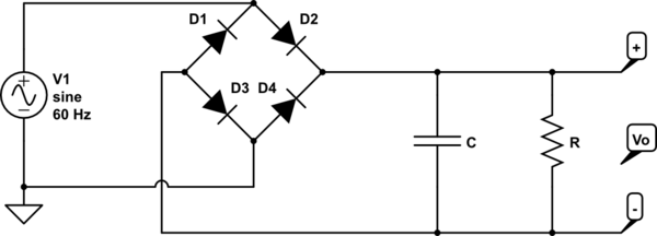
1
\$\begingroup\$

schematic

simulate this circuit – Schematic created using CircuitLab

Boylestad's book says that with the diodes conducting the effect of the resistor is "removed" so the \$RC\$ constant is so small that the capacitor charges with the value of of \$V_1\$ extremely fast. Is it a good approximation to say that it charges instantaneously regardless of the value of \$R\$ and \$C\$? Assuming ideal diodes, voltage sources, etc. This is mentioned in the section of clamper circuits with alternating constant voltage sources, would this be different with a sin wave?

If possible I would like to ask something else. Supposing a forward voltage drop of 0.6 in each diode, the peak voltage on Vo would be V1 - 0.6 - 0.6 = V1 - 1.2. If diodes are considered as ideal with 0V drop in forward bias, then Vo = V1 in this case. There is one exercise here made in my classroom where the peak voltage in Vo is different V1, assuming all diodes ideal with 0V drop, ideal sources, etc. Does it make sense? Could the capacitor not be fully charged by the end of a half-cycle? Thanks again.

\$\endgroup\$
7
  • 2
    \$\begingroup\$ There is still a time constant, and the C is still part of it, but the R isn't. Instead there is a different (usually much smaller) R composed of the sine wave source impedance, the forward resistance of the diodes, and the interconnecting wire. Whether that's "instantaneous" or not depends on the details. \$\endgroup\$
    – user16324
    Commented Oct 15, 2016 at 18:22
  • 1
    \$\begingroup\$ You should also understand that "charges with the value of V1" means the uni-directional peak value of the sine wave minus two forward diode drops. (Many books will tell you that the forward drop of an ideal diode is 0 volts; in My Book the forward voltage drop of an ideal diode is 0.6 volts, which is a lot closer to the ideal real world than 0 volts.) Uni-directional peak value for a perfect sine wave input (most line voltages are not) would be 1/2 the peak-to-peak voltage you see on an O-scope and definitely not the RMS voltage, which is what you read on a DVM connected to the AC source. \$\endgroup\$
    – FiddyOhm
    Commented Oct 15, 2016 at 18:37
  • 1
    \$\begingroup\$ Add to what they said: as Vmains rises above Vcap and diode starts to conduct Icap ~= V/r = (Vmains-Vcap) / (Rmains + Rwiring + ESR cap + ) = very large current peaks. Adding a small sreading resistor on series with HV out of bridge or in mains input helps. Without this in real world RFI peaks occur due to diode pulse currents. \$\endgroup\$
    – Russell McMahon
    Commented Oct 15, 2016 at 19:59
  • \$\begingroup\$ Thanks guys, that makes sense now. If possible I would like to ask something else. Supposing a forward voltage drop of 0.6 in each diode, the peak voltage on Vo would be V1 - 0.6 - 0.6 = V1 - 1.2. If diodes are considered as ideal with 0V drop in forward bias, then Vo = V1 in this case. There is one exercise here made in my classroom where the peak voltage in Vo is different V1, assuming all diodes ideal with 0V drop, ideal sources, etc. Does it make sense? Could the capacitor not be fully charged by the end of a half-cycle? Thanks again. \$\endgroup\$ Commented Oct 15, 2016 at 20:33
  • \$\begingroup\$ Don't forget that iIn real life, if C is very large the "inrush current" charging up C in the very first half-cycle after switch-on can be big enough to fry the diodes! \$\endgroup\$
    – alephzero
    Commented Oct 15, 2016 at 21:44

2 Answers 2

4
\$\begingroup\$

If V1 is a perfect voltage source and the diodes are also perfect, The effect of R is only removed when C is charging, which will be when the absolute value of V1 is greater than the voltage across C.

At any other time R will be discharging C, so R becomes visible and causes ripple in the output voltage.

\$\endgroup\$
2
  • \$\begingroup\$ Can I get the peak voltage at Vo by applying KVL? Or that value depends on the capacitance, period of the wave, etc? \$\endgroup\$ Commented Oct 15, 2016 at 20:53
  • 1
    \$\begingroup\$ @JoãoPedro: With a perfect voltage source, perfect diodes, a perfect load and a perfect capacitor, if the input voltage is given in volts, RMS, the peak output voltage will be, simply, \$ Vin \times \sqrt 2\$ \$\endgroup\$
    – EM Fields
    Commented Oct 16, 2016 at 5:59
1
\$\begingroup\$

The appropriate power diodes and low ESR electrolytic cap will have an ESR*C time constant of <10~100us while cheap e-caps rated for much lower ripple current (or no rating given) have higher ESR will be 200uS to >1000us.

So it is not instantaneous but fast. Lower ESR caps are always preferred due to I^2*ESR heat loss.

Meanwhile the load R * C time constant must be chosen for a reasonable ripple level such as 10% where it works out that RC must be>= 16/f for line frequency at bridge input. This results in very large peak currents at full load equal to % Vripple in duty cycle (d) and 1/d in peak charge currents.

Also,with at no load the caps will rise to 1.4*Vac rms at full load and also rise another 8~10% from Vac drop at rated load or in other words the Vdc can swing as much as 50% higher with no compared to full load.

There may be other formulas which determine Load R to Cap ESR ratios, but the C value must only sag 10% at 2f pulse rates for 10% full load ripple.

This is only 1/6th of the exponent RC time constant value slew time for a 60% decay in voltage hence 6T min is needed for 100Hz and 12T for for 50Hz. The bridge is a frequency doubler. The extra storage time to 16T is due approximation errors, voltage margin and cap value aging.

This is why we call it an unregulated power supply.

You can simulate your AC source peak voltage and f, add ESR to the cap with a fixed R and scope the results here.

\$\endgroup\$

Your Answer

By clicking “Post Your Answer”, you agree to our terms of service and acknowledge you have read our privacy policy.

Not the answer you're looking for? Browse other questions tagged or ask your own question.