2
\$\begingroup\$

I'm trying to self-learn EE and have a question:

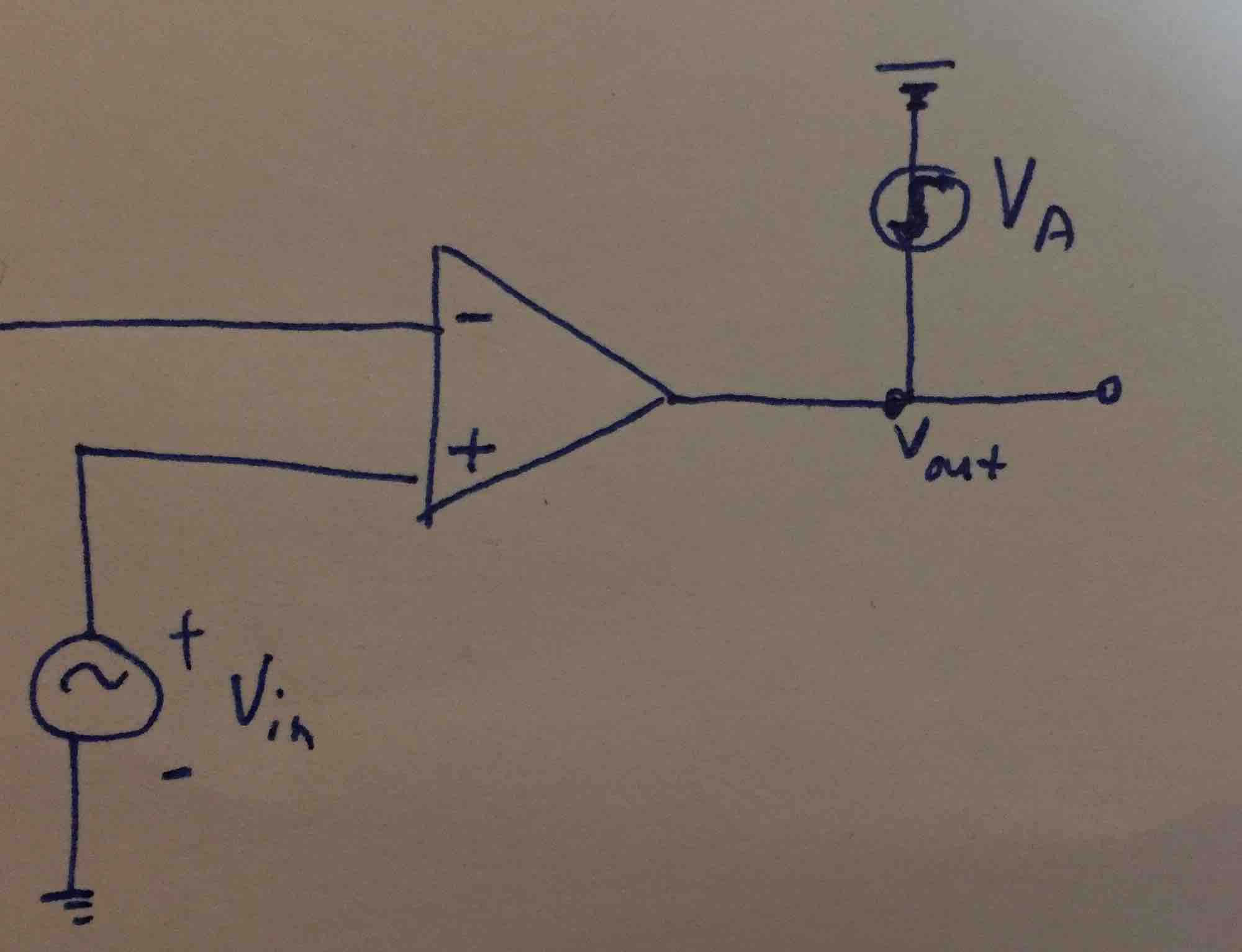
What happens if you add an external voltage source to the output of an op-amp? Say as in this picture: enter image description here

I know that WITHOUT the Va, Vout would just be Vin (is this a correct assumption? I'm assuming here that V+ = V- = Vin). However, we're adding a Va source, so would Vout just be Vin + Va?

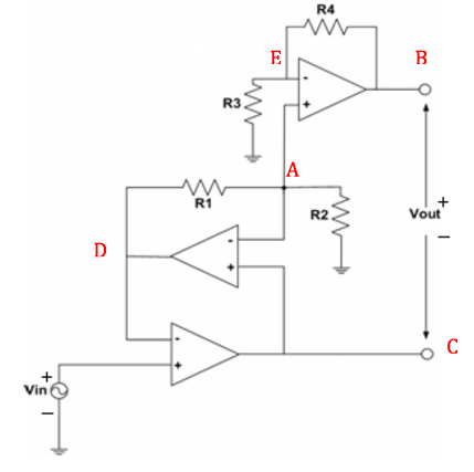
EDIT: to answer mga's question, I made up the circuit but it comes from thinking about enter image description here

The op-amp that I'm confused about is the bottom left one; the Vout of that op-amp is equal the voltage at the red A and I understand this mathematically but I don't understand it intuitively. Why wouldn't it be Vin + Va?

\$\endgroup\$
4
  • 1
    \$\begingroup\$ Are you sure that without Va, Vout would be just Vin ? Can you prove it mathematically ? Can you show me (or yourself) with numbers ? \$\endgroup\$
    – efox29
    Commented Dec 9, 2016 at 19:56
  • \$\begingroup\$ Is VA a drop from the supply voltage? What's the inverting input connected to? \$\endgroup\$
    – MGA
    Commented Dec 9, 2016 at 19:56
  • \$\begingroup\$ @MGA I just edited my question to clarify it \$\endgroup\$
    – Laura K
    Commented Dec 9, 2016 at 20:08
  • \$\begingroup\$ @efox29 I can't prove it mathematically but I know that Vout = A * (Vp - Vn). If Vout (without Va) is actually X according to that formula, why wouldn't it just be X + Va? \$\endgroup\$
    – Laura K
    Commented Dec 9, 2016 at 20:10

3 Answers 3

8
\$\begingroup\$

I think you're mixing up a few different concepts. Let's tackle them one at a time.

First, the output voltage of an op amp is indeed \$V_{out} = A_v \cdot (V_+ - V_-)\$. That's the definition of a differential amplifier. But in an op amp, \$A_v\$ is huge -- a million or more in some cases. Because of that, any negative feedback causes the op amp inputs to be very close to each other. This is the only condition that gives you a non-huge output voltage.

As for your complex circuit, there's no voltage source driving an op amp output. The middle op amp is acting as a non-inverting amplifier. The input is \$V_C\$ (the output of the bottom op amp) and the output is \$V_D\$. The relationship between them is:

$$V_D = V_C(1 + \frac {R_1}{R_2})$$

\$R_1\$ and \$R_2\$ form a voltage divider between \$V_D\$ and ground, with \$V_A\$ in the middle. The relationship is:

$$V_A = V_D \frac {R_2}{R_2 + R_1}$$

We know that \$V_D = V_{in}\$ and \$V_C = V_A\$. So what does that get us?

$$V_A = V_{in} \frac {R_2}{R_2 + R_1}$$

The bottom two op amps form a non-inverting attenuator -- an amplifier with a gain less than one. The output is \$V_A\$. This feeds into the top op amp, which acts as a non-inverting amplifier.

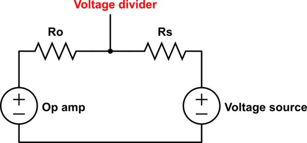
To answer your first question -- if you connect an ideal voltage source to an ideal op amp output, you break the rules of circuit theory and don't get a meaningful answer. In real life, what happens depends on how the voltage source and op amp are built. Probably it will be something like this:
schematic

simulate this circuit – Schematic created using CircuitLab

The output resistances of the op amp and voltage source will form a voltage divider between the two. These resistances will be small (and unpredictable), so lots of current will flow and you won't know what the voltage will be until you try it. Obviously, this is bad, so don't do it. :-)

UPDATE: Why is \$V_C\$ affected by \$V_D\$? Because \$V_D\$ is one of the inputs to the bottom op amp. Maybe you're confused because this seems like circular reasoning -- \$V_C\$ controls \$V_D\$, but \$V_D\$ also controls \$V_C\$. So how does \$V_C\$ "know" where to go if it doesn't know what \$V_D\$ is yet?

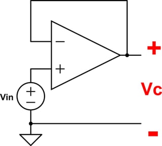
To improve your intuition, it might help to start with some simpler examples. Consider the basic voltage follower:
schematic

simulate this circuit

Imagine this circuit with \$V_{in}\$ powered off. \$V_{in}\$ and \$V_C\$ are both 0V. Now we turn on \$V_{in}\$. The non-inverting input's voltage becomes greater than the inverting input's voltage (\$V_+ > V_-\$). Because of the op amp's huge gain, the output shoots up. But the output is connected to the inverting input, so when it rises above \$V_{in}\$, you get \$V_- > V_+\$. This causes the output go to down again. So when the output is greater than the input voltage, it drops. When the output is less than the input voltage, it rises. The only stable state is when the output is (almost) equal to the input voltage.

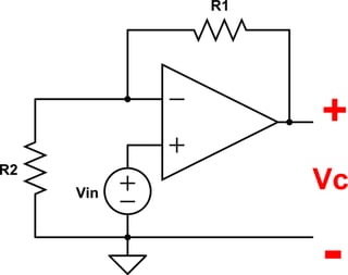
Now let's add some resistors:
schematic

simulate this circuit

This is a non-inverting amplifier. It works the same way as the voltage follower, but now the output has to be higher than \$V_{in}\$ to stabilize. (The stable state is really when \$V_- = V_{in}\$.) But adding resistors doesn't change the basic principle, right?

Now try this. Here's a really dumb voltage follower:
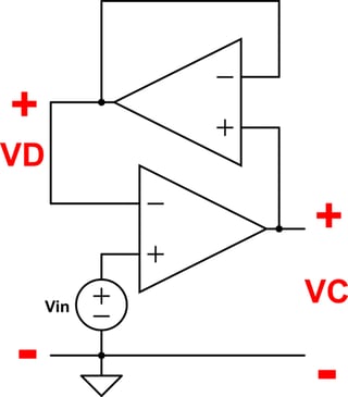
schematic

simulate this circuit

This looks complicated, but it really doesn't change anything. The bottom op amp's output rises, which causes the top op amp's output to rise. When the top op amp's output goes above \$V_{in}\$, the bottom op amp's output starts to fall, which makes the top op amp's output fall. The only stable state is where both op amp's outputs equal \$V_{in}\$.

Your circuit is like that, only the top op amp forms a non-inverting amplifier instead of a voltage follower:
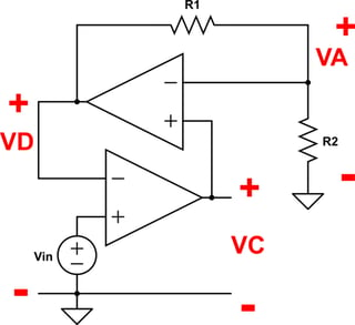
schematic

simulate this circuit

This is the same as the previous circuit, except now the bottom op amp's output has to be less than \$V_{in}\$ for the circuit to stabilize. For example, if both resistors are 1k, then:

$$V_D = V_{in}$$ $$V_A = V_C = \frac 1 2 V_{in}$$

Try changing any of those voltages and you'll have a voltage difference between the op amp inputs. For example, if the bottom op amp's output (\$V_C\$) goes up, the top op amp's output has to rise, because \$V_C > V_A\$. But that would make \$V_D > V_{in}\$, which means the bottom op amp's output has to fall again.

This concept of connecting an output back to an input is called negative feedback. It's widely used in electronics and mechanical control systems (among other things). There's a whole subfield of engineering called Control Systems that studies how to use negative feedback to improve the performance of a system and how to guarantee that it doesn't become unstable.

I found the ideal op amp rules very confusing when I first learned them. Hopefully these examples of transient behavior will help you make sense of things.
\$\endgroup\$
3
  • \$\begingroup\$ Thank you so much! This was really helpful in clarifying answers. I have a quick follow-up question: I'm confused why intuitively Vc is affected by Vd. The way it works in my mind is that the current starts from Vin at the bottom left, then goes through the bottom amp, to Vc, and then affects Vd. I don't see how Vd affects Vc. I understand it mathematically but I'm not getting it intuitively. In my mind, Vc should ONLY be determined by the op-amp at the bottom and Vin. \$\endgroup\$
    – Laura K
    Commented Dec 9, 2016 at 20:48
  • \$\begingroup\$ @LauraK I've updated my answer with a response. \$\endgroup\$
    – Adam Haun
    Commented Dec 9, 2016 at 23:21
  • \$\begingroup\$ @LauraK Also, remember that (almost) no current flows into either op amp input. So there's not really a direct current path between input and output. \$\endgroup\$
    – Adam Haun
    Commented Dec 10, 2016 at 4:41
5
\$\begingroup\$

If you add a voltage source to the output of an op-amp, you have two devices with low output impedance trying to drive a node to a certain voltage and both have theoretical infinite current source/sink capability. In the real world, your voltage source blows up your op-amp. End of story.

It's not X+Va because two voltage sources driving a node to two different voltages results in lots of energy getting dumped from one to the other. Voltages do not sum up to each other at nodes. If you take a 1.5 volt battery and a 9 volt battery and ground their negative terminals together and join their positive terminals, you don't end up with 10.5 volts. Instead the 9 volt battery starts dumping its energy into the 1.5V battery. The 1.5V battery starts "recharging" before it explodes.

bottom left one; the Vout of that op-amp is equal the voltage at the red A

Due to negative feedback of the two bottom op-amps, V_d will be driven by the bottom two op-amps to be equal to Vin. V_a will be driven by the middle op-amp to equal V_c. At no point is more than one op-amp driving any voltage node.

\$\endgroup\$
10
  • \$\begingroup\$ @LauraK If we assume that all of these op-amps are using negative feedback to achieve ideal op-amp values, the output of the bottom op-amp creates V_c. V_c should equal V_a because of the center op-amp. V_d should equal Vin due to the bottom op-amp. V_e should equal V_a (and V_c). I'm not sure what you're confused about. Can you clarify? At every node, there's only one voltage source driving the node voltage as far as I can tell. \$\endgroup\$
    – horta
    Commented Dec 9, 2016 at 20:57
  • \$\begingroup\$ thank you for taking the time to explain these elementary concepts to me. I understand everything you said above ^ but I don't understand why intuitively, Vc is affected by the middle op-amp. It seems to me that the current flows from Vin through the bottom op-amp to Vc. Why is Vc then changed to the value of Va? Why doesn't Va's value change to be Vc? Mathematically, I understand what's happening. But intuitively, it seems to me that we're just taking Vc and putting it as the value of Va and ignoring the effects of the bottom amp on Vc. \$\endgroup\$
    – Laura K
    Commented Dec 9, 2016 at 21:28
  • \$\begingroup\$ @LauraK We're not ignoring the effects of the bottom opamp on Vc. In negative feedback, an ideal op-amp is trying to drive the input terminals to be the same voltage no matter what. Therefore, the bottom opamp drives Vc to be whatever voltage is necessary to get Vd to equal Vin. The tricky part here is that as it is trying to drive Vc to be something that will cause Vd to equal Vin, the middle op-amp is driving Vd directly to be something else that will force Va to equal Vc. Eventually, a balance will be had and they will settle on a balance that will satisfy Va=Vc and Vd=Vin. \$\endgroup\$
    – horta
    Commented Dec 9, 2016 at 21:41
  • \$\begingroup\$ @LauraK Also note that in an op-amp, you should think of it as two separate but related circuit elements. There is no realistic current flow between input and output on an op-amp. The op-amp output gets its current and voltage from the power rails/ground. The input side is a measuring system with very high input impedance to try and eliminate the input side of the op-amp from affecting the circuit. This is how you should view the internals of an op-amp: en.wikipedia.org/wiki/Operational_amplifier#/media/… \$\endgroup\$
    – horta
    Commented Dec 9, 2016 at 21:46
  • \$\begingroup\$ Ohh "a balance will be had and they will settle on a balance that will satisfy Va = Vc and Vd = Vin" makes it all clear to me. Does this mean the solution set I read was incorrect when it stated that Vc = Va? (instead, Vc should be the balance value)? It seems to me that when the solution set says Vc = Va, it is ignoring the effect of the bottom op-amp, but when Vc = the value that balances as you said, it makes a lot more intuitive sense. \$\endgroup\$
    – Laura K
    Commented Dec 9, 2016 at 21:54
3
\$\begingroup\$

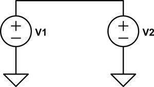
Since an op amp is just a voltage controlled voltage source, I can translate your question into a simpler one: What happens in the circuit below?

enter image description here

\$\endgroup\$
3
  • \$\begingroup\$ The primary quality of an ideal voltage source is that it enforces its voltage over the terminals :) \$\endgroup\$
    – neonzeon
    Commented Dec 9, 2016 at 20:31
  • \$\begingroup\$ Astoundingly good answer by reduction! \$\endgroup\$
    – Joshua
    Commented Dec 9, 2016 at 22:48
  • 1
    \$\begingroup\$ It's actually very scary - since both voltage sources have an infinite amount of power available to enforce their voltage, that simple circuit could blow up the universe as we know it. \$\endgroup\$
    – neonzeon
    Commented Dec 10, 2016 at 0:57

Your Answer

By clicking “Post Your Answer”, you agree to our terms of service and acknowledge you have read our privacy policy.

Not the answer you're looking for? Browse other questions tagged or ask your own question.