1
\$\begingroup\$

I'm in the process of leaning to design PCB's and leaning to solder tiny QFN parts. As part of this process, I'm trying to create a circuit with the TPS63001 (Datasheet) buck-boost converter, which I would like to use to power a ESP8266 (which requires 3.3v) by a lipo.

According to the datasheet, the circuit should be: enter image description here
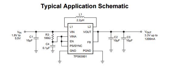
And in the same datasheet, they even provide a layout example: enter image description here
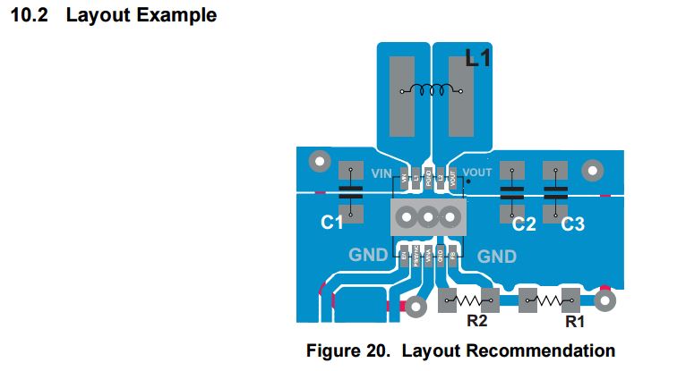
This layout is for the Adjustable Output Voltage version, I will be using the fixed voltage version.

With the information in the datasheet, I created this layout in eagle: enter image description here
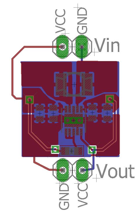
Now there are a few things I'm wondering:

  • There are three dots underneath the chip in the example in the datasheet. I guessed that these would be via's, and created a ground plane on the back of the board. I guess this is for heat dispensation, did I interpret this right?
  • I connected VINA, EN and PS/SYNC together. In the layout example EN and VINA just move out of the picture, but according to the schema, they should be connected, did I do this right?

Are there any other dising rules / recommendations that I should take care of?

\$\endgroup\$
4
  • \$\begingroup\$ Never use thermals in and around switching regulator components and it can compromise the performance. \$\endgroup\$ Commented Apr 1, 2017 at 17:13
  • \$\begingroup\$ ah, thermals are the 4 lines that connect some of the parts to the planes, right? It's something eagle did automagically, so I guess I have to figure out how to turn that option off. \$\endgroup\$
    – ErikL
    Commented Apr 1, 2017 at 17:24
  • \$\begingroup\$ Yup, those are thermals. Removing them will make soldering those parts somewhat more difficult. Can't comment on the necessity of leaving them out, though. \$\endgroup\$
    – JRE
    Commented Apr 1, 2017 at 17:36
  • \$\begingroup\$ Add some via stitching (Vias between the top and bottom ground areas) near the capacitor connections to ground. \$\endgroup\$
    – Dan Mills
    Commented Apr 1, 2017 at 19:37

1 Answer 1

3
\$\begingroup\$
  1. The dots under the chip are indeed vias, and most likely help conduct heat to the other side of the board - which should have a fairly large area to help dissipate the heat. They'll only help if you solder the exposed pad down, though. If you only solder the pads at the ends, it may not be enough.

  2. The current carrying traces should be wider as shown in layout from the datasheet, and as explained in the text in the datasheet.

  3. One of the examples shows Vina, EN, and PS tied together, and then connected to Vin through a 100 Ohm resistor. You have those three tied together, and that appears to be a resistor that connects them to Vin, OK. Pulling PS high disables the power save mode.

Those are the things that I (as a hobbyist) can see.

Eagle should have some kind of rules for trace widths. If you set the power carrying connections to the proper type in the schematic, then it should tell you (or force you) to use wider traces when laying out those connections. I don't use Eagle, though, so I can't say for sure what it does or how to set things up - most programs have some features along those lines, though.

\$\endgroup\$

Your Answer

By clicking “Post Your Answer”, you agree to our terms of service and acknowledge you have read our privacy policy.

Not the answer you're looking for? Browse other questions tagged or ask your own question.