2
\$\begingroup\$

I am trying to build a MOSFET based AC switching circuit, with multiple switching circuits running on the same DC power supply. Each switching circuit is basically an expanded solid state relay.

The MOSFETs are switching 240V 50Hz AC (UK Mains) at ~300mA (though the design should take up to 4A in theory).

Each switching circuit on it's own works exactly as intended but when placed together on the same +5/GND bus each circuit interacts with & partially activates the others.

My current theory is that some transient voltage is making it back through the circuit somewhere to the gates of MOSFETs that are meant to be off.

The best I can describe the symptom is that when switching circuit A is 'on' and switching circuit 'B' is off, the load connected to the switched live on circuit 'B' buzzes at 50Hz, I assume getting a half wave of AC power. One of the MOSFETs in circuit B also gets extremely hot implying flow either backwards through the diode or through the gate.

I've included the circuit diagram I'm working with, the opto isolators are controlled by an IC but I've simplified that side of the circuit to a connector as I've powered the optos with other means and still had the same problem.

Is there an obvious solution I'm missing? I feel like I'm doing something stupid. Any ideas how I could better isolate the gates from each other?


Some clarification of the circuit if you need:

  • AC Live is attached to pin 1 of both P1 and P2
  • Each switched live is attached to pin 2 of P1 and P2 seperately
  • The dashed line is simply to clarify where the low voltage control circuit is isolated from the high voltage switching circuits.
  • U1 is a 5V DC-DC isolator (ROE-0505S)
  • The diodes D1 and D2 are my attempt to stop 240V mains making it from one circuit to another through the shared ground connection, removing them or replacing them with a large resistor makes no difference to the symptoms.

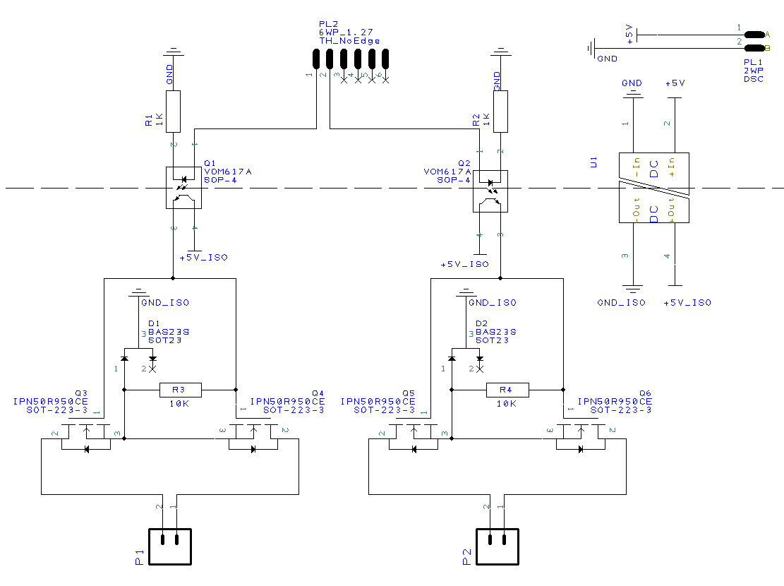
Circuit diagram of experimental dual MOSFET AC switching circuit

\$\endgroup\$
2
  • 1
    \$\begingroup\$ What's your switching rate? Have you looked at photovoltaic isolators instead of the optocouplers? \$\endgroup\$ Commented Jul 27, 2017 at 22:51
  • \$\begingroup\$ Photovoltaic isolators is a very interesting option, I'm looking into them now as Transistor suggested below. Currently I'm just switching them on/off with human reaction time being the limiting factor so, 1Hz or less. My eventual target however is a leading/trailing edge dimming circuit so that would be switching at ~100Hz but with a rise/fall time of less than 40μs. \$\endgroup\$
    – Mudf4ce
    Commented Jul 27, 2017 at 23:18

3 Answers 3

2
\$\begingroup\$

John Birckhead has answered your question correctly, I think.

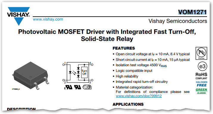
You may be able to solve the problem, eliminate the isolated power supplies and simplify your circuit using a photovoltaic MOSFET driver.

enter image description here

Figure 1. Extract from VOM1271 datasheet.

I haven't studied this and would be interested in comments on performance of these devices.

\$\endgroup\$
2
  • \$\begingroup\$ This is a very interesting option. I'll have a look at/play with them and let you know about anything interesting I find. \$\endgroup\$
    – Mudf4ce
    Commented Jul 27, 2017 at 23:21
  • 3
    \$\begingroup\$ In looking into PV MOSFET Drivers I've also discovered another family of isolated drivers that seem to do exactly the same thing but without photovoltaics, the Silicon Labs SI8752 for example. I have no idea how these work yet but another interesting option to look into. \$\endgroup\$
    – Mudf4ce
    Commented Jul 27, 2017 at 23:37
3
\$\begingroup\$

When the circuit is off, q3 and q4 are off. When you turn on P1, the sources of q3 and q4 are riding on the 220V power line, and the gate is (power line + 5) volts. This means that GND_ISO and +5V_ISO must also follow the power line, taking Q5 and Q6 with them. Whatever your load is remains referenced to neutral, so Q5 will have high gate-drain voltage in the wrong direction or just act like a rectifier through Q5 body diode if D2 is not present.

You will need separate isolated supplies.

\$\endgroup\$
2
  • \$\begingroup\$ That is what I suspected was happening, good to have it confirmed. I was really rather hoping someone would have a way around it other than separate isolated supplies (mostly for cost reasons) oh well, thank you very much for your input, I'll have a look at photovoltaic isolators as others have mentioned. \$\endgroup\$
    – Mudf4ce
    Commented Jul 27, 2017 at 23:04
  • \$\begingroup\$ Good luck and let us know how it goes. \$\endgroup\$ Commented Jul 28, 2017 at 11:50
0
\$\begingroup\$

You need separate DC-DC converter for each AC switch.

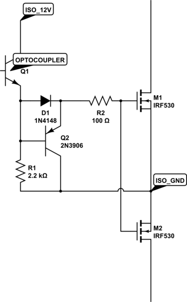
5V supply for the gate is low - your MOSFET has 3.5V gate threshold, and the optocoupler will drop some. Working near the threshold, when you want switching is not a good idea. Better choose 12V DC-DCs.

A better gate driver would be useful, even made with discrete components.

schematic

simulate this circuit – Schematic created using CircuitLab

\$\endgroup\$
1
  • \$\begingroup\$ Good point, I originally had the opto pulling the MOSFETs low for this reason. I'll put together a better driving circuit eventually, this fairly dodgy one has just made prototyping/experimenting with my multiple switching circuit problem easier. \$\endgroup\$
    – Mudf4ce
    Commented Jul 27, 2017 at 23:09

Your Answer

By clicking “Post Your Answer”, you agree to our terms of service and acknowledge you have read our privacy policy.

Not the answer you're looking for? Browse other questions tagged or ask your own question.