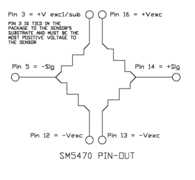
I have worked with basic resistive sensors before, but I have never seen a pinout like this one and I'm not sure how the voltages work for these pins. I was told it may be a resistive bridge, but it seems to me there are some differences between this one and the examples I've seen in articles. I also don't see much of an explanation in the datasheet for this sensor (a pressure sensor):
http://www.mouser.com/ds/2/589/-219572.pdf
I am not sure what other terms I can search for to understand how to use this sensor in my project. Is it a resistive bridge? If so, how does this one differ from a basic example (i.e. why does it seem to be separated down the middle instead of connected?). What is the theory of operation? What are the meanings of +V exc, -V exc, +Sig, -Sig and so on? Any information would be helpful!

